Phase shift circuit and phase correcting method

Active Publication Date: 2007-04-05
SOCIONEXT INC
View PDF2 Cites 1 Cited by
  • Summary
  • Abstract
  • Description
  • Claims
  • Application Information

AI Technical Summary

Benefits of technology

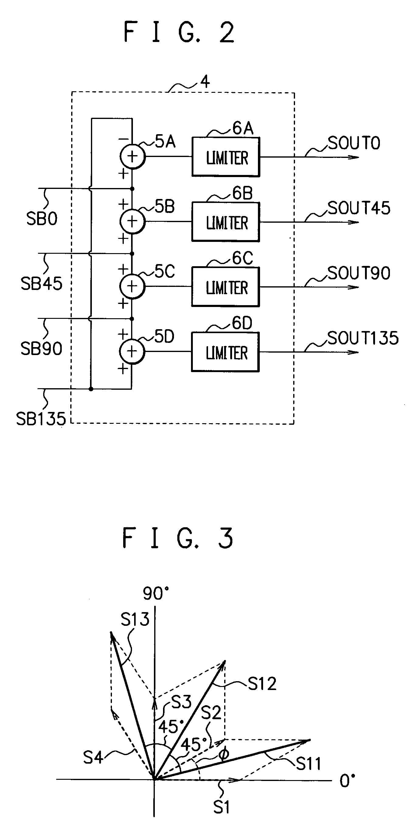
[0019] According to the present invention, by the vector synthesis of the signals which are supposed to have a 45° phase difference, out of the plural orthogonal phase signals having u

Problems solved by technology

Consequently, a DC offset occurs due to local self-mixing using the signals with the same frequency, and by this DC offset, a subsequent-stage circuit may possibly be saturated to stop its operation.
Therefore, even if the primary CR-type 45° phase shifter 64 is designed so that a desired frequency characteristic is obtained, the resistance values of the resistors and the capacitance values of the capacitors are actually influenced by manufacturing (process) variation and parasitic components,

Method used


Image

  • Phase shift circuit and phase correcting method
  • Phase shift circuit and phase correcting method
  • Phase shift circuit and phase correcting method

Examples


Example

First Embodiment

[0055]FIG. 4 is a view showing a configuration example of a 45° phase shift circuit in a first embodiment of the present invention. The 45° phase shift circuit has a 45° / 90° phase shifter 11, two 90° phase correctors 12, and a 45° phase corrector 13.

[0056] The 45° / 90° phase shifter 11 is a primary CR-LPF type 45° / 90° phase shifter for phase-shifting an input signal by an integral multiple of 45°, and receives differential input signals IN, INX to output a 0° signal SC0, a 45° signal SC45, a 90° signal SC90, and a 135° signal SC135 supposed to have 0°, 45°, 90°, and 135° relative phase differences respectively at a center frequency f0. That is, the 45° / 90° phase shifter 11 receives the differential input signals IN, INX to output the four-phase signals SC0, SC45, SC90, and SC135 with the frequency f0, having a phase difference of about 45°.

[0057] The 45° / 90° phase shifter 11 is constituted of a CR network including resistors R1˜R4 and capacitors C1˜C4, and circuits...

Example

Second Embodiment

[0091] Next, a second embodiment will be described.

[0092]FIG. 10 is a diagram showing a configuration example of a 45° phase shift circuit in the second embodiment of the present invention. The 45° phase shift circuit in the second embodiment has a 45° phase shifter 41, 90° phase shifters 42, 43, 90° phase correctors 44, 45, and a 45° phase corrector 46.

[0093] The 45° phase shifter 41 is a primary CR-type 45° phase shifter constituted of a CR network, in which circuits each constituted of one resistor Ri and one capacitor Ci (i=any integer out of 41-44) connected in series are connected in parallel between signal lines through which differential input signals IN, INX are inputted.

[0094] The 45° phase shifter 41 receives the differential input signals IN, INX to output a 0° signal SF0, a 45° signal SF45, a 180°signal SF180, and a 2250 signal SF225 which are supposed to have 0°, 45°, 180°, and 2250 relative phase differences respectively. Incidentally, resistance ...


PUM


Abstract

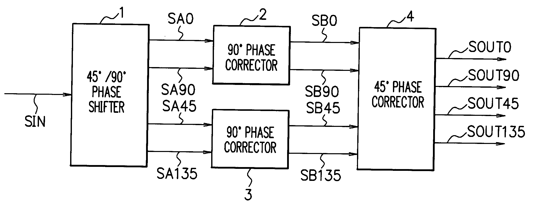
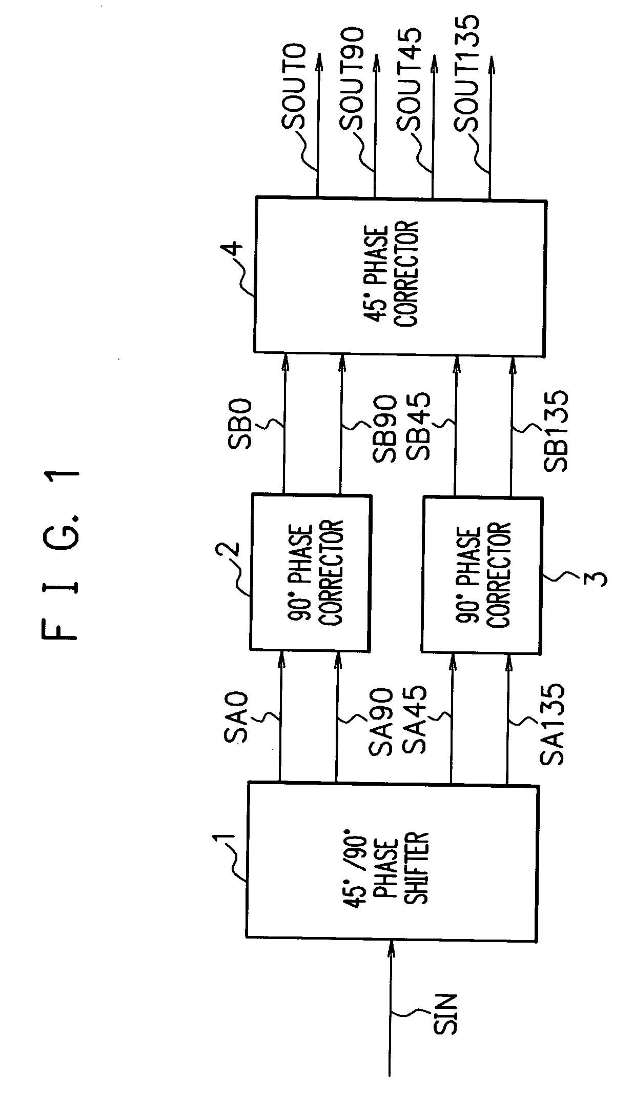
A phase shift circuit includes a 45° phase corrector that performs vector synthesis of signals supposed to have a 45° phase difference, out of a plurality of sets of orthogonal phase signals having an about 45° phase difference and an equal amplitude, the orthogonal phase signals in each set having undergone 90° phase correction, and outputs signals resulting from the vector synthesis, whereby a phase error between the orthogonal phase signals in the different sets is eliminated by the vector synthesis to make it possible to correct their phase difference to accurately 45°.

Description

TECHNICAL FIELD [0001] The present invention relates to a phase shift circuit and a phase correcting method, more particularly, to those suitably applied to a 45° phase shift circuit that generates a plurality of signals having a 45° phase difference. BACKGROUND ART [0002] In a receiver and the like for wireless communication such as mobile communication, a direct conversion (zero IF) method is a desirable reception method. Being simple in circuit configuration and requiring no IF (Intermediate Frequency) filter, the direct conversion method can realize cost reduction. [0003] However, a typical direct conversion receiver that has been conventionally used mixes local oscillation signals having the same frequency as that of an inputted high-frequency signal (reception signal) to take out a desired low-frequency signal. Consequently, a DC offset occurs due to local self-mixing using the signals with the same frequency, and by this DC offset, a subsequent-stage circuit may possibly be s...

Claims


Application Information

Patent Timeline
IPC IPC(8): H01P9/00
CPCH03H7/21
Inventor TOMITA, KAZUHIRO
Owner SOCIONEXT INC
Why Eureka
Try Eureka