Camera module with contamination reduction feature

a technology of camera module and feature, applied in the field of electronic devices, can solve the problems of reducing affecting the quality of captured images, so as to reduce the passage of contaminants, reduce the contamination of the image capture device, and limit contaminants

Active Publication Date: 2008-07-03
NANCHANG O FILM OPTICAL ELECTRONICS TECH CO LTD
View PDF13 Cites 22 Cited by
  • Summary
  • Abstract
  • Description
  • Claims
  • Application Information

AI Technical Summary

Benefits of technology

[0015]The boot and the receiving portion of the housing function together as a means of limiting contaminants that might otherwise reach the image capture surface of the image capture device. The receiver portion of the housing includes a first inner surface and a second inner surface. The inner perimeter of the first inner surface is smaller than the perimeter of the second inner surface, with the first inner surface being disposed between the second inner surface and the image capture device. The boot extends from a position surrounded by the first inner surface of the housing to a position surrounded by the second inner surface of the housing. For example, in some embodiments, the boot extends past the end (e.g., bottom surface) of the lens unit, so that at least a portion of the inner surface of the second end of the boot is spaced apart from the lens unit (e.g., closer to the image capture device). A contaminant collection surface (e.g., a ledge with a V-shaped channel) joins the first inner surface and the second inner surface. The outer surface of the second end of the boot engages (e.g., slidably abuts) the first inner surface of the opening in the housing. The second end of the boot remains in contact with the first inner surface of the housing is moved with respect to the image capture device (e.g., along the optical axis during a focus operation). The contact between the second end of the boot and the first inner surface of the housing reduces the passage of contaminants between the lens unit and the housing to the image capture device.
[0016]The first end of the boot contacts the lens unit. For example, the boot can be stretched over the end of the lens unit so as to remain in place via frictional engagement. Optionally, the first end of the boot can be fixed to the lens unit with an adhesive or a mechanical attachment device. Alternatively, the boot can be fixed to the housing and slidably contact the lens unit, but this approach may be less effective at reducing contamination of the image capture device.
[0017]In an example embodiment, the receiver portion of the housing includes a first cylindrical wall and a second cylindrical wall, which are coaxial. The first cylindrical wall has an inner diameter that is smaller than the inner diameter of the second cylindrical wall and is disposed closer to the image capture device than the second cylindrical wall. The second end of the boot is coupled to the housing by an exterior surface of the second end of the boot slidably engaging the first cylindrical wall. The top edge of the first cylindrical wall is joined to the bottom edge of the second cylindrical wall by a ledge, which serves as a particle trap. In a particular embodiment, the ledge defines a channel that enhances its functionality as a particle trap.

Problems solved by technology

Although camera modules that are focused via thread sets provide for relatively accurate focal adjustments, they still have disadvantages.
For example, as the lens unit is rotated within the housing, sliding friction between threads creates particulate debris that could easily contaminate the image sensor and / or other optical components (e.g., infra-red filters, protective covers, other lenses, etc.).
Consequently, these contaminants accumulate and noticeably degrade the quality of images captured by, for example, blocking light to the image sensor.
It should be noted that although threaded components are used here as an example, other types of focusing components can similarly produce particulate debris that reduces the quality of the captured images.
In addition to particulate debris produced by friction, ramped housings are also susceptible to other contaminants.
For example, adhesives used to fix lens units to housings can easily run down into the camera module and contaminate the imaging components.
Ramped modules are particularly susceptible to fluid contamination because the interface between the lens unit and the housing is typically not as tight as that of threaded camera modules.
Further, it is unlikely that the camera module will remain upright during use, thus debris is free to fall back out of the groove and obstruct the image sensor and / or optics.
Alternatively, the boot can be fixed to the housing and slidably contact the lens unit, but this approach may be less effective at reducing contamination of the image capture device.

Method used


Image

  • Camera module with contamination reduction feature
  • Camera module with contamination reduction feature
  • Camera module with contamination reduction feature

Examples


Embodiment Construction

[0028]The present invention overcomes the problems associated with the prior art by providing a digital camera module including a boot disposed between the lens unit and the housing, so as to reduce contaminants entering the camera module, which might degrade the quality of images captured. In the following description, numerous specific details are set forth (e.g., particular examples of focus devices, substrate types, attachment devices, etc.) in order to provide a thorough understanding of the invention. Those skilled in the art will recognize, however, that the invention may be practiced apart from these specific details. In other instances, details of well known camera module manufacturing practices (e.g., automated focus processes, materials selection, molding processes, etc.) and components (e.g., electronic circuitry, device interfaces, etc.) have been omitted, so as not to unnecessarily obscure the present invention.

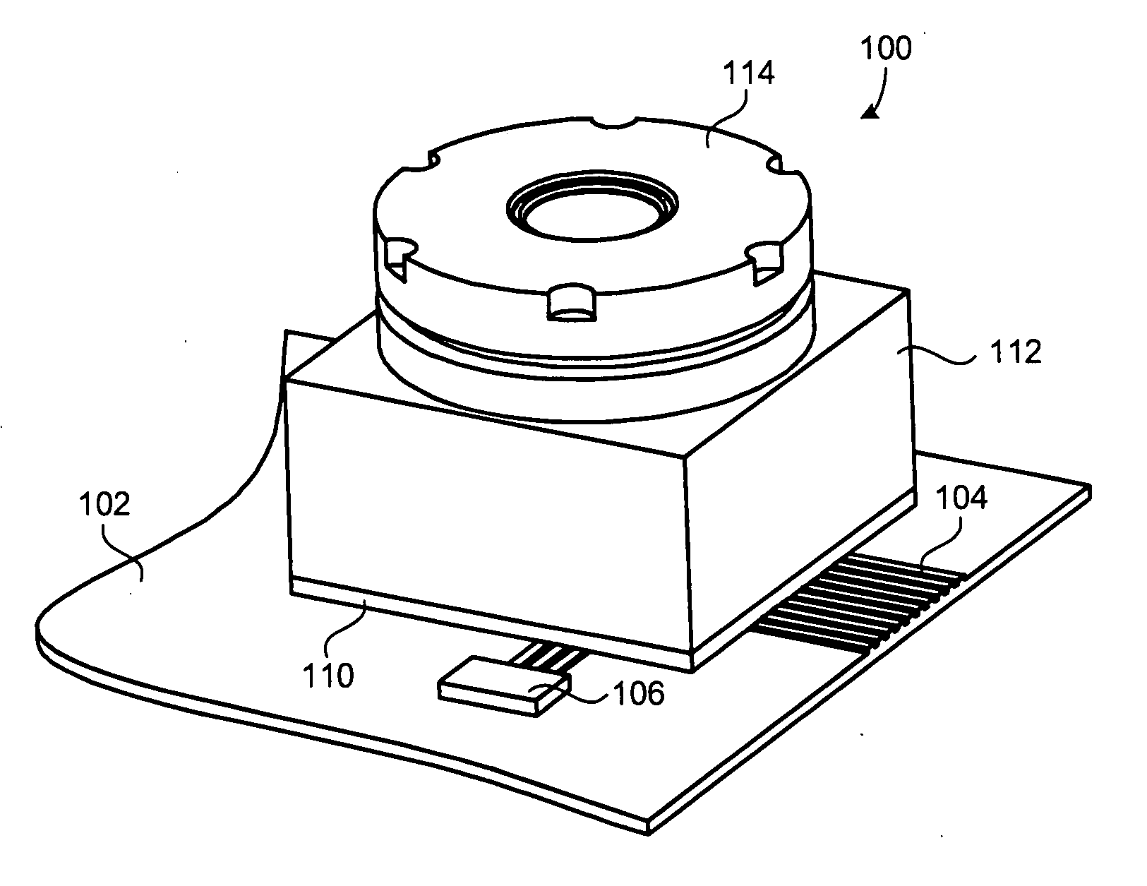
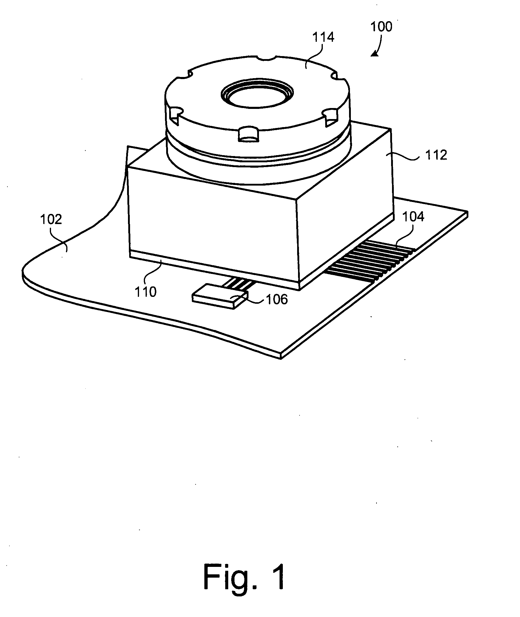
[0029]FIG. 1 is a perspective view of a camera module 100 ...


PUM

PropertyMeasurementUnit
perimeteraaaaaaaaaa
distanceaaaaaaaaaa
outer perimeteraaaaaaaaaa

Abstract

A novel digital camera module includes an image capture device, a lens unit, a housing including an opening for receiving the lens unit and positioning the lens unit with respect to the image capture device, and a boot coupled the lens unit and the housing. In a particular embodiment, the boot includes an upper end and a lower end, each of which has a different outer perimeter. In another particular embodiment, a portion of the inner surface of the boot remains free of contact from the outer surface of the lens unit. In another particular embodiment, the lower end of the boot extends beyond the lower end of the lens unit.

Description

RELATED APPLICATIONS[0001]This application claims the benefit of prior U.S. Provisional Patent Application Ser. No. 60 / 864,348, filed on Nov. 3, 2006 by at least one common inventor, which is incorporated herein by reference in its entirety.BACKGROUND OF THE INVENTION[0002]1. Field of the Invention[0003]The present invention relates generally to electronic devices, and more particularly to digital camera modules. Even more particularly, the present invention relates to a system for focusing a digital camera module that prevents debris and particulate matter produced by the focusing process from contaminating the sensor array of an image capture device.[0004]2. Description of the Background Art[0005]Digital camera modules are currently being incorporated into a variety of electronic devices. Such camera hosting devices include, but are not limited to, cellular telephones, personal data assistants (PDAs), and computers. The demand for digital camera modules continues to grow as the ab...

Claims


Application Information

Patent Timeline
Patent Type & Authority Applications(United States)
IPC IPC(8): G03B17/02
CPCG03B17/02Y10T29/49826H04N5/2257H04N23/57
Inventor WESTERWECK, LOTHAR R.CHUA, ALBERT JOHN Y.AFSHARI, BAHRAM
Owner NANCHANG O FILM OPTICAL ELECTRONICS TECH CO LTD
Why Eureka
Try Eureka