Method of determining when a mobile station is ready to be served during a handoff in a wireless communications network

Active Publication Date: 2008-07-03
WSOU INVESTMENTS LLC
View PDF4 Cites 46 Cited by
  • Summary
  • Abstract
  • Description
  • Claims
  • Application Information

AI Technical Summary

Problems solved by technology

However, as mobility or speed of the UE increases, the CPICH Ec/Nt may be less

Method used


Image

  • Method of determining when a mobile station is ready to be served during a handoff in a wireless communications network
  • Method of determining when a mobile station is ready to be served during a handoff in a wireless communications network
  • Method of determining when a mobile station is ready to be served during a handoff in a wireless communications network

Examples


Embodiment Construction

[0023]In order to better understand the present invention, an example of a conventional uplink frame structure for a UMTS wireless communication system and an example communication flow diagram of a conventional downlink channel quality reporting will be described, followed by descriptions of example processes of estimating when a given UE switches from a current serving base station to a next serving base station during a handoff based on a comparison of measured energy levels where channel quality reporting is expected for the current serving base station and the next serving base station.

Conventional UMTS Uplink Frame Structure

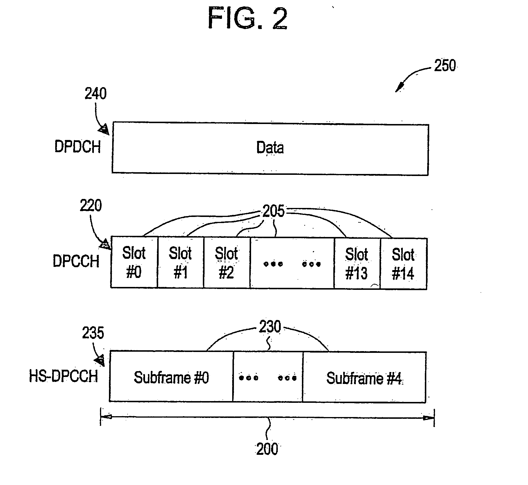
[0024]FIG. 2 illustrates an example of a frame 200 of a UMTS uplink dedicated traffic channel 250 including a DPDCH 240, a DPCCH 220 and a high speed dedicated physical control channel (HS-DPCCH) 235. Each frame 200 may have a length of, for example, 10 milliseconds (ms) and, for the DPCCH 220, may be partitioned into a plurality of slots 205 (e.g., 15 slot...


PUM


Abstract

A method of determining handoff of a user equipment (UE) to a transferee serving station from a transferor serving station at the transferee serving station is provided. The transferee serving station (e.g., a Node B) measures an energy level in a first portion of an uplink channel (e.g., an uplink high-speed dedicated physical control channel (HS-DPCCH)), the first portion of the uplink channel associated with the transferee serving station. In an example, the first portion of the uplink channel is where a channel quality indicator (CQI) is expected to be reported from the UE for the transferee serving station. The transferee serving station also measures an energy level in a second portion of the uplink channel, the second portion of the uplink channel associated with the transferor serving station. In an example, the second portion of the uplink channel is where a CQI is expected to be reported from the UE for the transferor serving station. The transferee serving station then determines when the UE has handed off to the transferee serving station based upon the measured energy levels.

Description

BACKGROUND OF THE INVENTION[0001]1. Field of the Invention[0002]Example embodiments of the present invention relate generally to a method of determining when a mobile station is ready to be served during a handoff in a wireless communications network.[0003]2. Description of the Related Art[0004]A cellular communications network typically includes a variety of communication nodes coupled by wireless or wired connections and accessed through different types of communications channels. Each of the communication nodes includes a protocol stack that processes the data transmitted and received over the communications channels. Depending on the type of communications system, the operation and configuration of the various communication nodes can differ and are often referred to by different names. Such communications systems include, for example, a Code Division Multiple Access 2000 (CDMA2000) system and Universal Mobile Telecommunications System (UMTS).[0005]UMTS is a wireless data communi...

Claims


Application Information

Patent Timeline
IPC IPC(8): H04Q7/20H04W36/30
CPCH04W36/30H04W24/08
Inventor BRUECK, STEFANDOMINIQUE, FRANCISKONG, HONGWEINABHANE, WALID ELIAS
Owner WSOU INVESTMENTS LLC
Why Eureka
Try Eureka