Car structure

a technology for cars and structures, applied in the direction of axle-box lubrication, railway bodies, windows, etc., can solve the problems of high stress on the face plate, concentrated deformation due to vertical load, etc., to avoid the increase in the weight of the structure, the side structure can be light in weight, and the thickness of the second joint part can be increased.

Inactive Publication Date: 2008-07-10
NAKAMURA HIDEYUKI +3
View PDF3 Cites 4 Cited by
  • Summary
  • Abstract
  • Description
  • Claims
  • Application Information

AI Technical Summary

Benefits of technology

[0012]According to the present invention, because it is not necessary to increase plate thickness of the vehicle outer faceplate and the vehicle inner faceplate of the side structure, a car structure having the required strength against vertical load can be provided while avoiding increase in weight of the structure.
[0013]In other words, according to this car structure, two face plates of the hollow member are coupled by the first joint part so that they can withstand the vertical load. Therefore, two face plates may be thin and thereby the side structure can be light in weight.
[0014]In addition, by increasing thickness of the second joint part, concentration of deformation and generation of high stress in this part can be suppressed.

Problems solved by technology

As a result, deformation due to vertical load is concentrated and high stress is generated on the face plate which is sandwiched between the robust hollow member and entrance frame.

Method used


Image

  • Car structure
  • Car structure
  • Car structure

Examples


embodiment 1

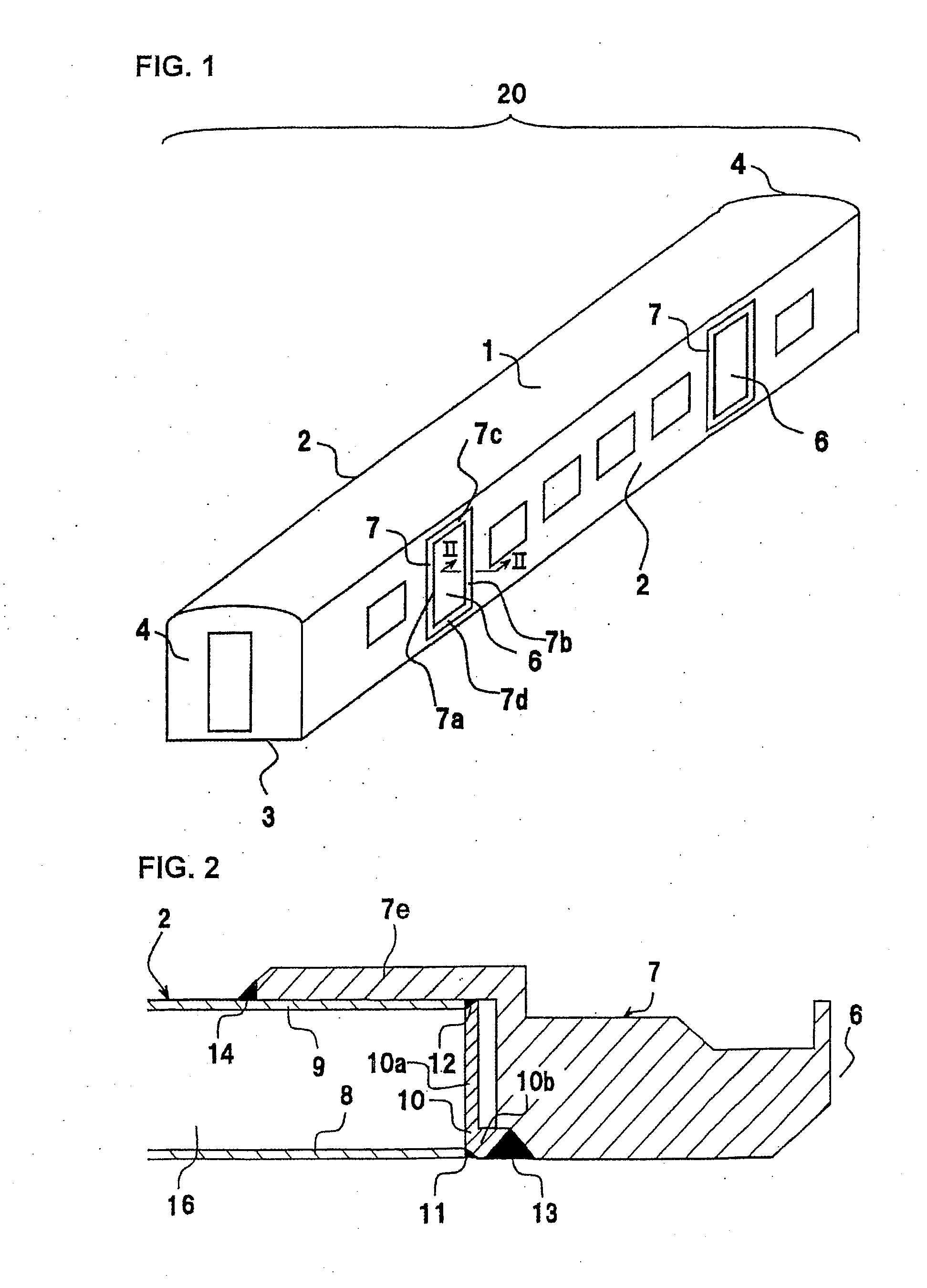
[0021]A first embodiment of the present invention will be described with reference to FIGS. 1 to 3.

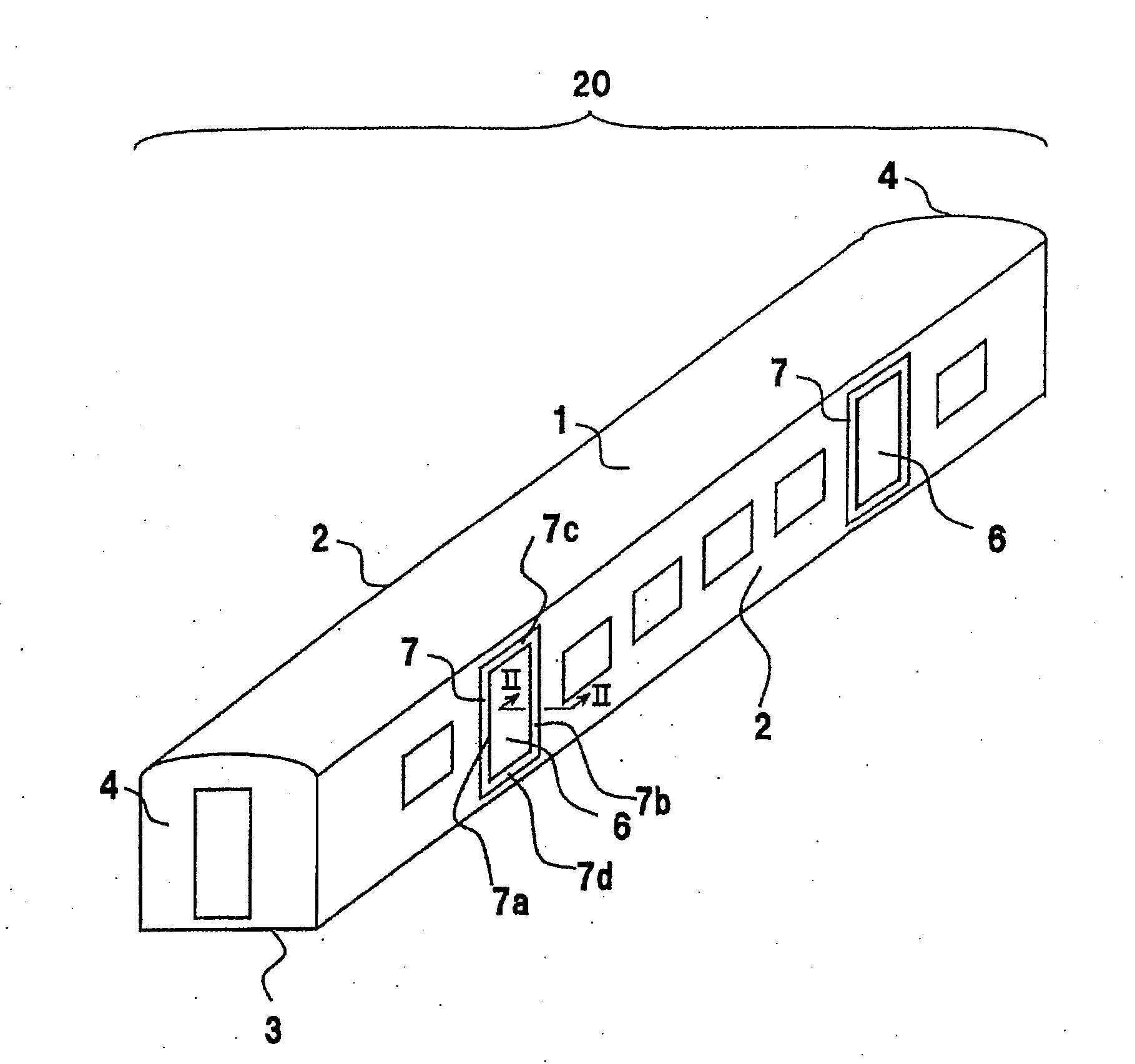
[0022]In an embodiment shown in FIG. 1, a rail car structure 20 comprises a roof component 1 forming an upper side, two side structures 2, 2 forming lateral sides, an underframe 3 forming a lower side, and two end components 4, 4 forming end sides.

[0023]Each of the roof component 1, the side structures 2, 2, the underframe 3, and the end components 4, 4 is formed by jointing (welding or friction stir welding) a plurality of extruded members.

[0024]The extruded members forming the roof component 1, the side structures 2, 2, and the underframe 3 are hollow members made of aluminum alloy and the hollow members are extruded in a longitudinal direction of the railroad car structure 20. The extruded members forming the end components 4, 4 are single materials with ribs made of aluminum alloy and the single materials are extruded in a vertical direction of the railroad car structure 20.

[0025]F...

embodiment 2

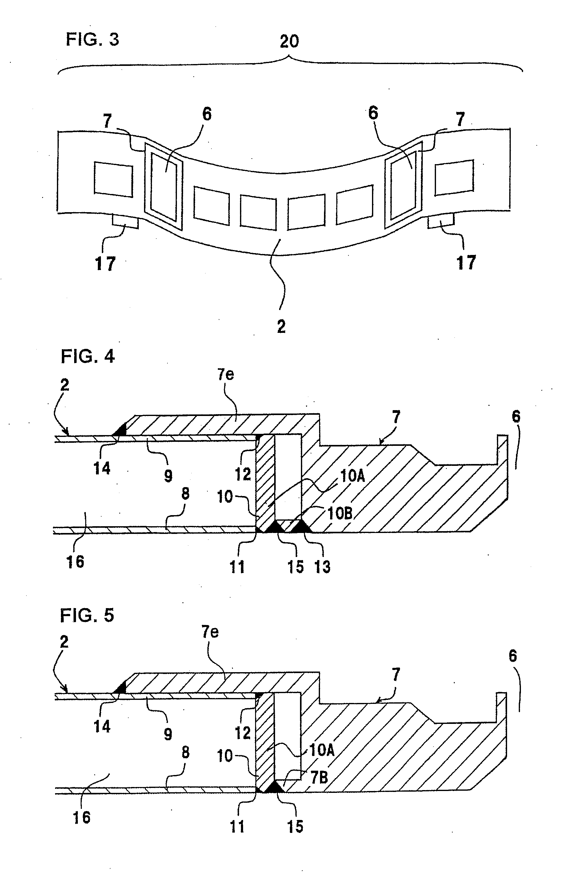
[0036]A second embodiment of the present invention will be described with reference to FIG. 4.

[0037]In the second embodiment, the L-shaped fitting 10 in the embodiment in FIG. 2 is composed of a first joint part 10A and a second joint part 10B which are two separate members. In the embodiment in FIG. 4, the first joint part 10A and the second joint part 10B are in the form of plates and it is not necessary to form an L-shaped fitting 10 with cut-out members or extruded members as in FIG. 2. Therefore, the material and processing cost can be reduced. The first joint part 10A and the second joint part 10B are butt welded as shown by a welded part 15 so that they are coupled to form an L-shape in a cross section perpendicular to the opening edge as shown in the figure. Although the plate 10B is welded to the plate 10A here, the plate 10B may be welded to the face plate 8.

embodiment 3

[0038]A third embodiment of the present invention will be described with reference to FIG. 5.

[0039]In the third embodiment, the second joint part 10B in the second embodiment is integrally formed with the frame 7. In other words, the second joint part is provided as a projecting part 7B which projects from the frame 7 towards the side structure 2. The first joint part 10A and the second joint part 7B are welded by a welded part 15 and coupled to form an L-shape in a cross section perpendicular to the opening edge. According to the third embodiment, the L-shaped fitting can be easily formed and the processes of jointing the second joint part 7B can be reduced, in comparison to the first embodiment shown in FIG. 2.

[0040]Although jointing of the plate members has been described as welding in the above described embodiments, friction stir welding may be used instead of welding. Here, jointing means welding or friction stir welding.


PUM


Abstract

A car structure is provided which has the required strength against vertical load and vibration while avoiding increase in weight of the structure. At an entrance 6 of the railroad car structure 20 in which a side structure 2 is formed by a hollow member, the side structure 2 and a frame 7 are coupled via an L-shaped fitting 10. The L-shaped fitting 10 consists of a first joint part 10a which is in the form of a plate and couples a vehicle outer face plate 8 and a vehicle inner face plate 9 and a second joint part 10b which is in the form of a plate and butt welds a part of the first joint part 10a near the vehicle outer face plate 8 and the frame 7. Plate thickness of the second joint plate 10b is larger than plate thickness of the vehicle outer face plate 8. As a result, the required strength against vertical load can be ensured without increasing the plate thickness of the vehicle outer face plate 8, in other words, with little increase in weight of the structure.

Description

[0001]The present application is based on and claims priority of Japanese patent application No. 2007-002628 filed on Jan. 10, 2007, the entire contents of which are hereby incorporated by reference.BACKGROUND OF THE INVENTION[0002]1. Field of the Invention[0003]The present invention relates to a car structure forming a rail vehicle such as a railroad vehicle or a monorail car, and in particular relates to a car structure configured by jointing hollow members made of aluminum alloy, for example.[0004]2. Description of the Related Art[0005]A car structure comprises a roof component forming an upper side, two side structures forming lateral sides, an underframe forming a lower side, and two end components forming end sides in a longitudinal direction.[0006]Recently, for the main purposes of weight reduction and improvement in manufacturability of a rail vehicle, hollow extruded members made of aluminum alloy have been used for the roof component, the side structures, and the underfram...

Claims


Application Information

Patent Timeline
Patent Type & Authority Applications(United States)
IPC IPC(8): B61D17/08
CPCB61D17/08B61D17/041B61D17/00B61D17/04B61D17/06
Inventor NAKAMURA, HIDEYUKIMIYAMOTO, TOSHIHARUMOCHIDA, TOSHIHIKOKAWASAKI, TAKESHI
Owner NAKAMURA HIDEYUKI
Why Eureka
Try Eureka