Power system of single-rotor helicopter without reactive torque tail rotor

A power system and anti-torque technology, which is applied in the direction of rotorcraft, aircraft power transmission, aircraft power plant, etc., can solve the problems of complex double rotor mechanism, flight speed limitation, and large tail rotor noise.

Inactive Publication Date: 2021-03-26
王泽民
View PDF0 Cites 2 Cited by
  • Summary
  • Abstract
  • Description
  • Claims
  • Application Information

AI Technical Summary

Problems solved by technology

In order to reduce the power consumption of the tail rotor to balance the rotational torque of the body, the lengthened tail is used to increase the leverage distance between the rotor main shaft and the tail rotor to reduce the power consumption of the tail rotor, and in order to ensure the safety of the rotor rotation, the rotor and tail A certain safety distance is required between the propellers, so the tail of the traditional helicopter is too long, the power transmission distance of the tail rotor is long, the volume ratio of the tail structure is large, the weight is high, the flight speed is relatively slow, and the maneuverability is relatively poor. Existence of tail slurry: tail slurry is noisy, easily hurts ground personnel, and tail slurry is easy to colli

Method used


Image

  • Power system of single-rotor helicopter without reactive torque tail rotor
  • Power system of single-rotor helicopter without reactive torque tail rotor
  • Power system of single-rotor helicopter without reactive torque tail rotor

Examples


Embodiment 1

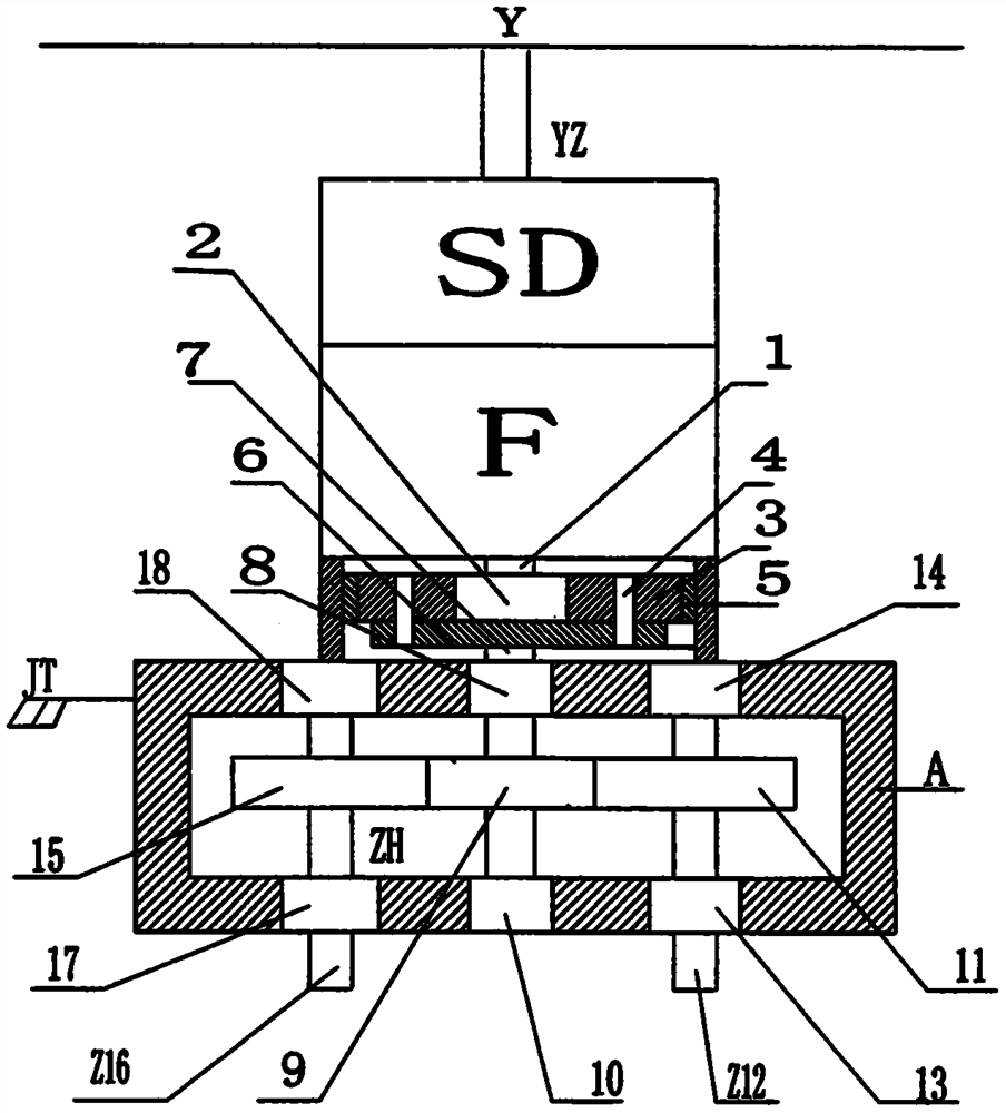
[0034] A power system for a single-rotor helicopter with no counter-torque tail rotor, which consists of a body, an engine, a paddleless torque balancer, a single rotor, the body is connected to the engine, and the upper part of the engine is connected to the transmission mechanism. The above is the prior art For helicopters, the lower part of the engine (F) is connected to a combined speed reducer (ZH), and the combined speed reducer (ZH) has one to five rotor shafts (YZ) that rotate in the opposite direction to the rotor shaft (YZ). The output shaft of the axis, the output shaft of the combined reducer (ZH) is connected to the load mechanism with the same casing, and the casing (A) of the combined reducer is connected to the body (JT) and connected to the body (JT) form a relative equilibrium torque.

Embodiment 2

[0036] The power system of a single-rotor non-reactive-torque tail rotor helicopter described in embodiment 1, the combined speed reducer (ZH) is composed of a planetary speed reduction unit and a parallel shaft speed reduction unit, and the first to five The root power output shaft is centered on the middle gear in the parallel shaft reduction unit, and its peripheral teeth are evenly distributed at 360 degrees to engage with one to five output gears or output gear sets, and the output gears or output gear sets are connected to the output shaft , based on the principle that its rotation direction is opposite to the rotation direction of the rotor shaft (YZ), taking the combined double-shaft output reducer (ZH) included in the combined reducer as an example: the lower output shaft (1) of the engine is connected to the combined double-shaft The sun gear (2) of the output reducer, the sun gear (2) is connected to at least three star gears (3-3) at 120 degrees to each other, and t...

Embodiment 3

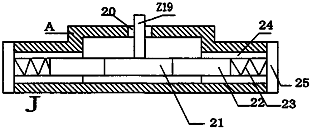
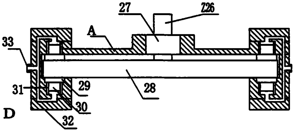
[0038] The power system of a single-rotor non-reverse torque tail rotor helicopter described in embodiment 1 or 2, the load mechanism includes: a radial plunger mechanism (J) in the medium pressure technology, and a radial plunger mechanism (J) in the power transmission technology. Various clutches, couplers, coupling couplings, disc brake mechanisms (D) in brake technology, or combined load mechanisms (DJ) composed of two of them, with one of the above load mechanisms Institutions come to specific applications,

[0039]Concrete application of radial injection plug type load mechanism (J) in this helicopter power system: one, on the described combined type biaxial output reducer housing (A) with output shaft (Z16), (Z12) as At least two cylinders (24-4) are evenly distributed in the center, and the plunger (22-4) is slidably connected in the cylinder (24-4), and the inner top of the cylinder (24-4) is connected with the plunger (22-4). ) is connected to the spring (23-4) betw...


PUM


Abstract

Aiming at some practical defects of overlong tail, long power transmission distance, slower speed, poorer maneuverability and the like of a traditional helicopter which balances the rotating torque ofthe helicopter body by utilizing reverse torque tail paddles and mutual reverse rotation of double coaxial rotors, the invention provides a power system of a single-rotor helicopter without the reactive torque tail rotor and a power system of a helicopter with a thrust propeller or a tilting thrust propeller, the reactive torque tail rotor of the traditional helicopter is replaced, one rotor in the double coaxial rotors is used for balancing the rotating torque of the helicopter body, and the flying speed and maneuverability of the helicopter are improved.

Description

Technical field: [0001] The invention relates to the aviation field, in particular to a power system of a single rotor helicopter. Background technique: [0002] During the use of the helicopter, the body will rotate and lose lift, resulting in a crash. In order to balance the rotational torque of the body, the traditional helicopter uses a variable pitch propeller at its tail to balance the rotational torque of the body. In order to reduce the power consumption of the tail rotor to balance the rotational torque of the body, the lengthened tail is used to increase the leverage distance between the rotor main shaft and the tail rotor to reduce the power consumption of the tail rotor, and in order to ensure the safety of the rotor rotation, the rotor and tail A certain safety distance is required between the propellers, so the tail of the traditional helicopter is too long, the power transmission distance of the tail rotor is long, the volume ratio of the tail structure is lar...

Claims


Application Information

Patent Timeline
IPC IPC(8): B64C27/06B64C27/12B64D35/02B64D35/00
CPCB64C27/06B64C27/12B64D35/00B64D35/02
Inventor 王泽民
Owner 王泽民
Why Eureka
Try Eureka