
Dome-Shaped Contact and Multi-Step Operation Electrical Switch Incorporating the Same

a multi-step operation, electrical switch technology, applied in the direction of snap-action arrangement, contact surface shape/structure, switch side location, etc., can solve the problem of difficult miniaturization of the switch, and achieve the effect of preventing restoration failure, reducing the pressing force temporarily, and easy miniaturization of the overall size of the switch

Inactive Publication Date: 2008-07-10
JAPAN AVIATION ELECTRONICS IND LTD
View PDF13 Cites 41 Cited by
  • Summary
  • Abstract
  • Description
  • Claims
  • Application Information

AI Technical Summary

Benefits of technology

[0015]Since the pressing force is temporarily reduced when one dome portion is depressed according to the present invention, a click feel can be provided. Since the pressing force varies with the dome portions, a multi-step operation can be achieved. In addition, since the elastic plate has a plurality of dome portions and a plurality of spacer portions formed integrally therewith, the overall size of the switch can be readily miniaturized. Furthermore, since the first and second dome portions have the respective inclined portions (spacer portions) along the outer peripheries thereof, and the inclined portions support the dome portions at the outer peripheries thereof, a restoration failure can be prevented, and thus, a stable operation can be achieved in that respect.

Problems solved by technology

Furthermore, since the legged movable plate 20 has the two legs 22 that protrude significantly from the main body 21, the size of the whole legged movable plate 20 is large, and accordingly, miniaturization of the switch is difficult.

Method used


Image

  • Dome-Shaped Contact and Multi-Step Operation Electrical Switch Incorporating the Same
  • Dome-Shaped Contact and Multi-Step Operation Electrical Switch Incorporating the Same
  • Dome-Shaped Contact and Multi-Step Operation Electrical Switch Incorporating the Same

Examples


first embodiment

[0064]FIGS. 3A to 3C show an embodiment of dome-shaped contact used in a multi-step operation electrical switch according to the present invention. According to this embodiment, a dome-shaped contact 60 is formed by press-working an elastic metal plate, comprises a first dome portion 61, a first spacer portion 62 formed along the outer periphery of the first dome portion 61, a second dome portion 64 formed at the center of the first dome portion 61 with a second spacer portion 63 interposed between the first dome portion 61 the second dome portion 64, and has a circular contour as a whole. For example, a spring stainless steel plate is used for the elastic metal plate forming the dome-shaped contact 60. In addition, to achieve higher conductivity, at least areas of the underside of the dome portions 61 and 64 in which contact portions 65 and 66 are to be formed may be plated with Ni, or Ag and Ni. The metal used for plating is not limited to these metals, and other metals can be use...

second embodiment

[0077]An embodiment shown in FIGS. 7A to 7D will be described. According to this embodiment, a plurality of openings 68 are formed in the first dome portion 61 in order that the pressing force during the first-step switching operation is reduced, and the first dome portion 61 can be deformed and depressed with a smaller load. Referring to FIG. 7A, two approximately semicircular-arch-shaped openings 68 are formed along the inner periphery of the first dome portion 61. Similarly, referring to FIGS. 5B and 5C, four and eight arch-shaped openings 68 are arranged and formed along the inner periphery of the dome portion 61, respectively. Referring to FIG. 5D, eighteen circular openings 68 are arranged and formed along the inner periphery of the dome portion 61.

[0078]The number of openings 68 can be appropriately determined as shown in FIGS. 7A to 7D. However, in terms of stability of the second dome portion 64, the configuration shown in FIG. 5B, in which the second dome portion 64 is sup...

third embodiment

[0081]FIG. 8A shows an example of the present invention, in which a protrusion 67 extending in the direction opposite to the direction in which the second dome portion 64 bulge is formed at the center of the second dome portion 64. If the protrusion 67 is formed on the surface facing the fixed contact 73 in this way and used as a contact portion to come into contact with the fixed contact 73, the contact reliability can be improved.

[0082]FIG. 8B shows a state in which a foreign body 75 having got into the dome-shaped contact 60 exists on the fixed contact 73 for illustration. Even if such a foreign body 75 gets into the dome-shaped contact 60, the protrusion 67 can ensure the contact (electrical connection) between the second dome portion 64 and the fixed contact 73. While one protrusion 67 is formed in this embodiment, a plurality of protrusions 67 may be formed near the center of the dome portion 64.

[0083]FIG. 9A is a plan view of the dome-shaped contact 60 with one protrusion 67 ...


PUM


Abstract

The present invention relates to a multi-step operation electrical switch having an elastic conductive plate, which is deformed to establish an electrical contact when a pressing force is applied thereto and is restored to the initial state to break the electrical contact when the pressing force is removed.According to the present invention, the elastic plate has a plurality of dome portions formed integrally therewith, each of the dome portions bulges in the direction opposite to the direction in which the elastic plate is pressed and is depressed by the pressing force applied thereto. The applied pressing force varies with the dome portions. In order to prevent an electrical contact from being established when no pressing force is applied to the elastic plate, spacer portions are necessary. According to the present invention, inclined spacer portions are provided along the outer peripheries of a first and a second dome portions, respectively.Therefore, since the pressing force is temporarily reduced when one dome portion is depressed, a click feel can be provided. Since the pressing force varies with the dome portions, a multi-step operation can be achieved. In addition, since the elastic plate has a plurality of dome portions and a plurality of spacer portions formed integrally therewith, the overall size of the switch can be readily miniaturized.

Description

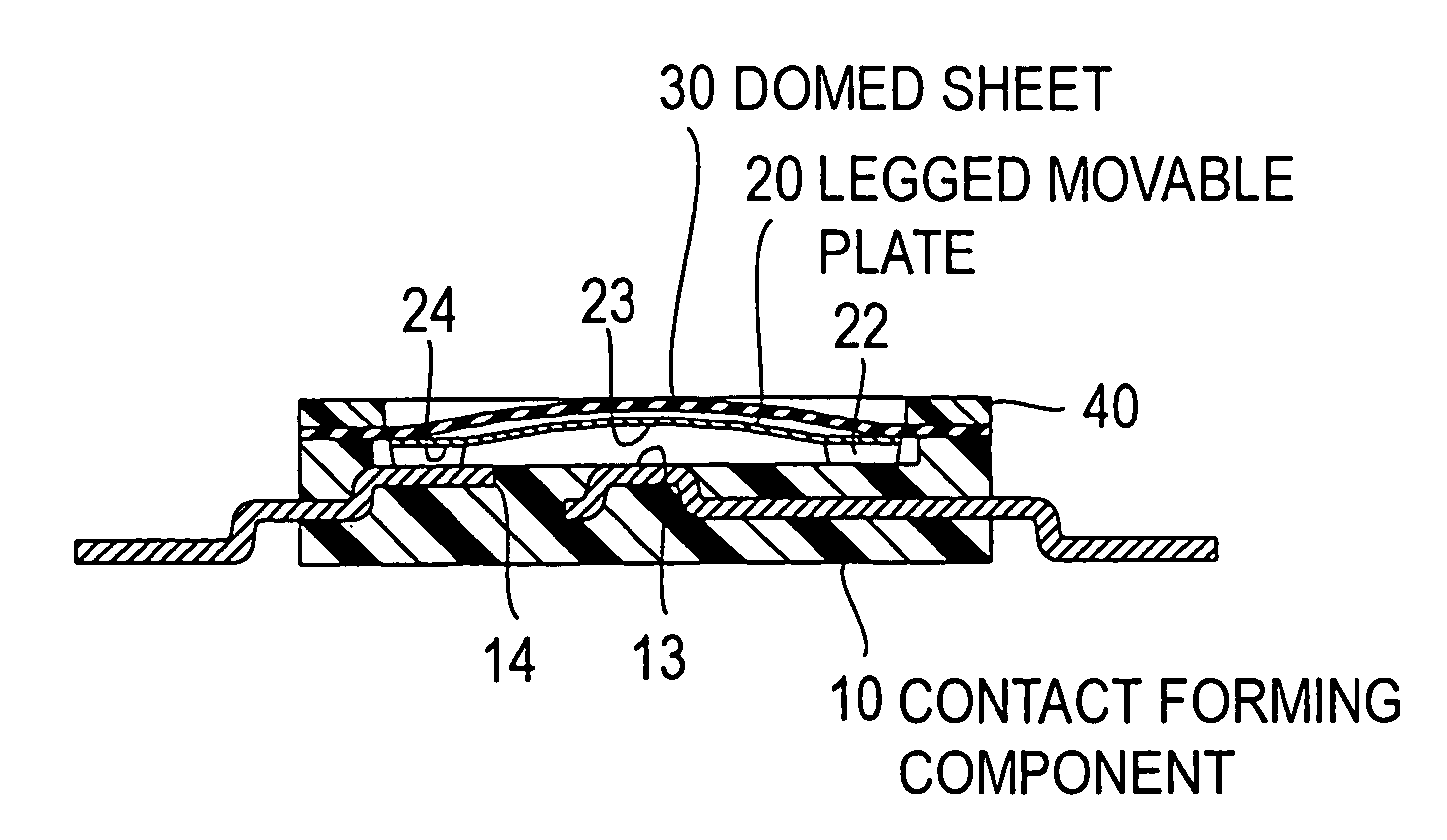
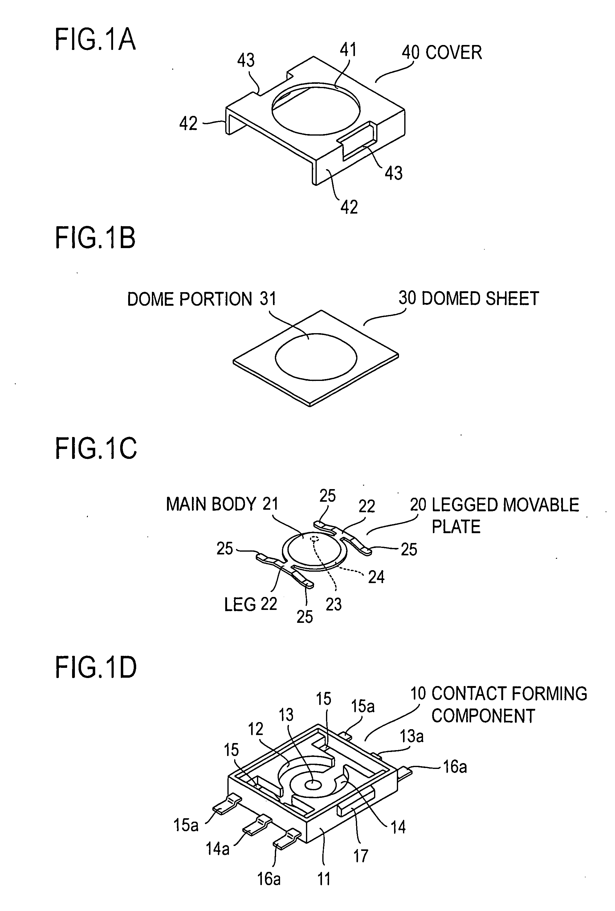
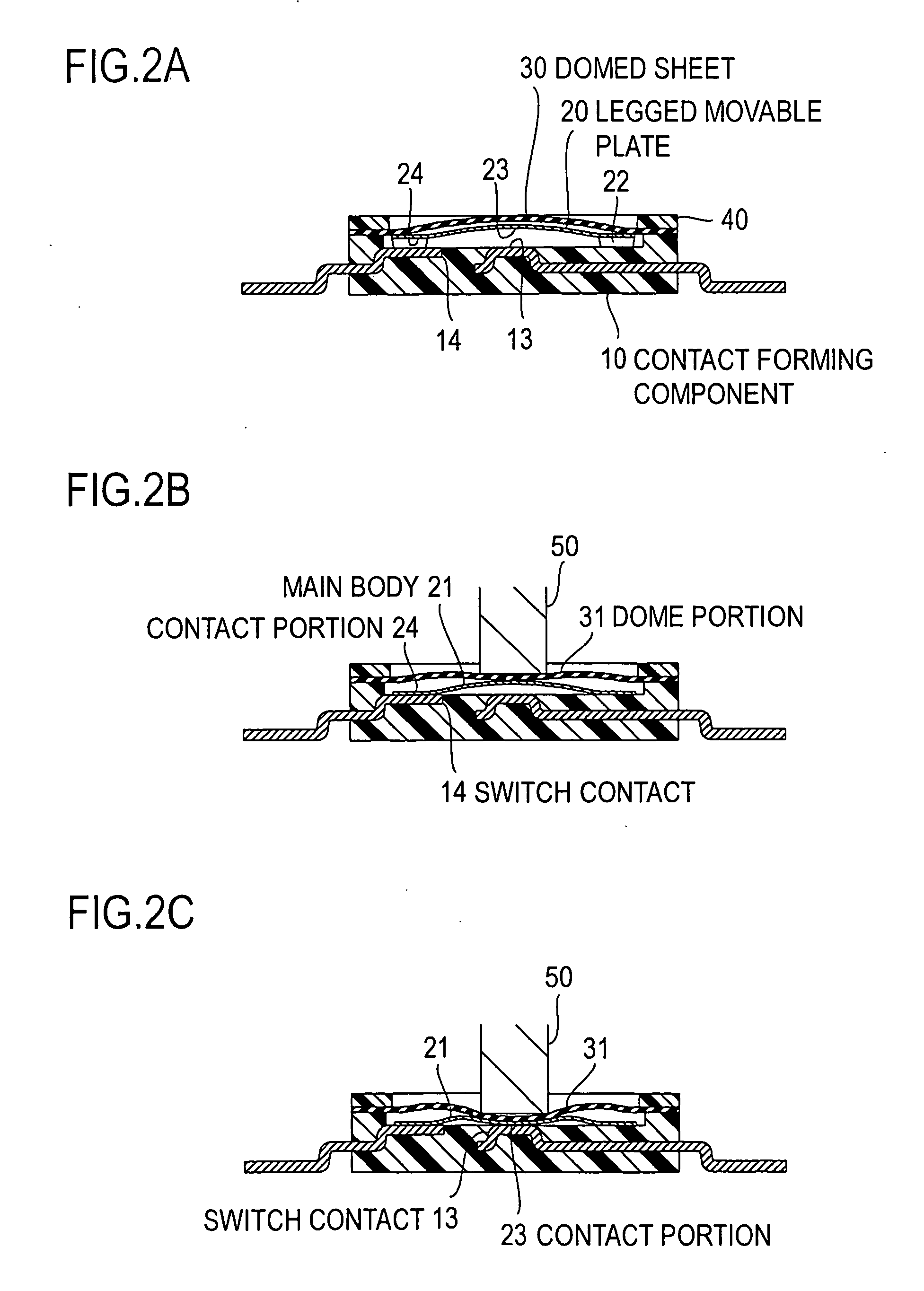
TECHNICAL FIELD[0001]The present invention relates to a dome-shaped contact that provides a multi-step operation, in particular, a two-step operation and an electrical switch incorporating the same.BACKGROUND ART[0002]FIGS. 1A to 1D show components of a switch described in the patent literature 1 as a conventional example of such a two-step operation switch. In this example, the switch comprises a contact forming component 10, a legged movable plate 20 and a domed sheet 30 housed in the contact forming component 10, and a cover 40 placed over these components.[0003]The contact forming component 10 comprises a resin mold 11 and a switch plate, which constitutes a switch contact, is insert-molded in the resin mold 11. At the bottom of a circular center part of a recess 12, there are disposed and exposed a circular switch contact 13 and an arch-shaped switch contact 14 surrounding the circular switch contact 13. In addition, at the bottom of the edges of straight line-shaped parts of t...

Claims


Application Information

Patent Timeline
Patent Type & Authority Applications(United States)
IPC IPC(8): H01H13/14H01H5/30H01H13/48H01H13/64H01H13/66
CPCH01H13/44H01H13/48H01H2225/018H01H2215/016H01H13/64
Inventor HAYAFUNE, ISAO
Owner JAPAN AVIATION ELECTRONICS IND LTD
Learn More