
Wound In-Situ Moulded Magnet End Coil and Method for Production Thereof

Active Publication Date: 2008-07-10
SIEMENS HEALTHCARE LTD
View PDF3 Cites 4 Cited by
  • Summary
  • Abstract
  • Description
  • Claims
  • Application Information

AI Technical Summary

Benefits of technology

[0020]One object of the present invention, therefore, is to provide a new end coil structure, and a new method for forming end coils, wh

Problems solved by technology

The known moulded end coils may suffer from quenches particularly in turns near the coil's inner radius.
Moulded coils are known to be relatively inaccurate.
This may be caused by differential shrink of the impregnating material during curing.
The use of moulded coils mounted onto a former leads to the probability of patchy contact between the coil and the former.
The patchy contact may cause these forces to deform the coil or the former at points of high local stress.
This yielding may cause a quench.
The combination of high forces and patchy contact may also combine to cause some circumferential movement of the coil, which again may lead to a quench, or departure of the magnetic field characteristics from the optimal situation.
However, such arrangements have suffered from certain drawbacks, some of which will now be briefly described.
However, this tight grip may in fact be the source of quench events, if the end coil moves during operation—a so-called stick-slip event.
The moulded end coils have to be wound separately from the rest of the solenoidal magnet, which increases machine set-up time and makes turns balancing more difficult.
Due to tolerance stack-up on the parts of the typical multi-part mould for the end coils, and non-uniform shrinkage of the resin impregnant during gelling, curing and cooling of

Method used


Image

  • Wound In-Situ Moulded Magnet End Coil and Method for Production Thereof
  • Wound In-Situ Moulded Magnet End Coil and Method for Production Thereof
  • Wound In-Situ Moulded Magnet End Coil and Method for Production Thereof

Examples


Example

DETAILED DESCRIPTION OF THE DRAWINGS

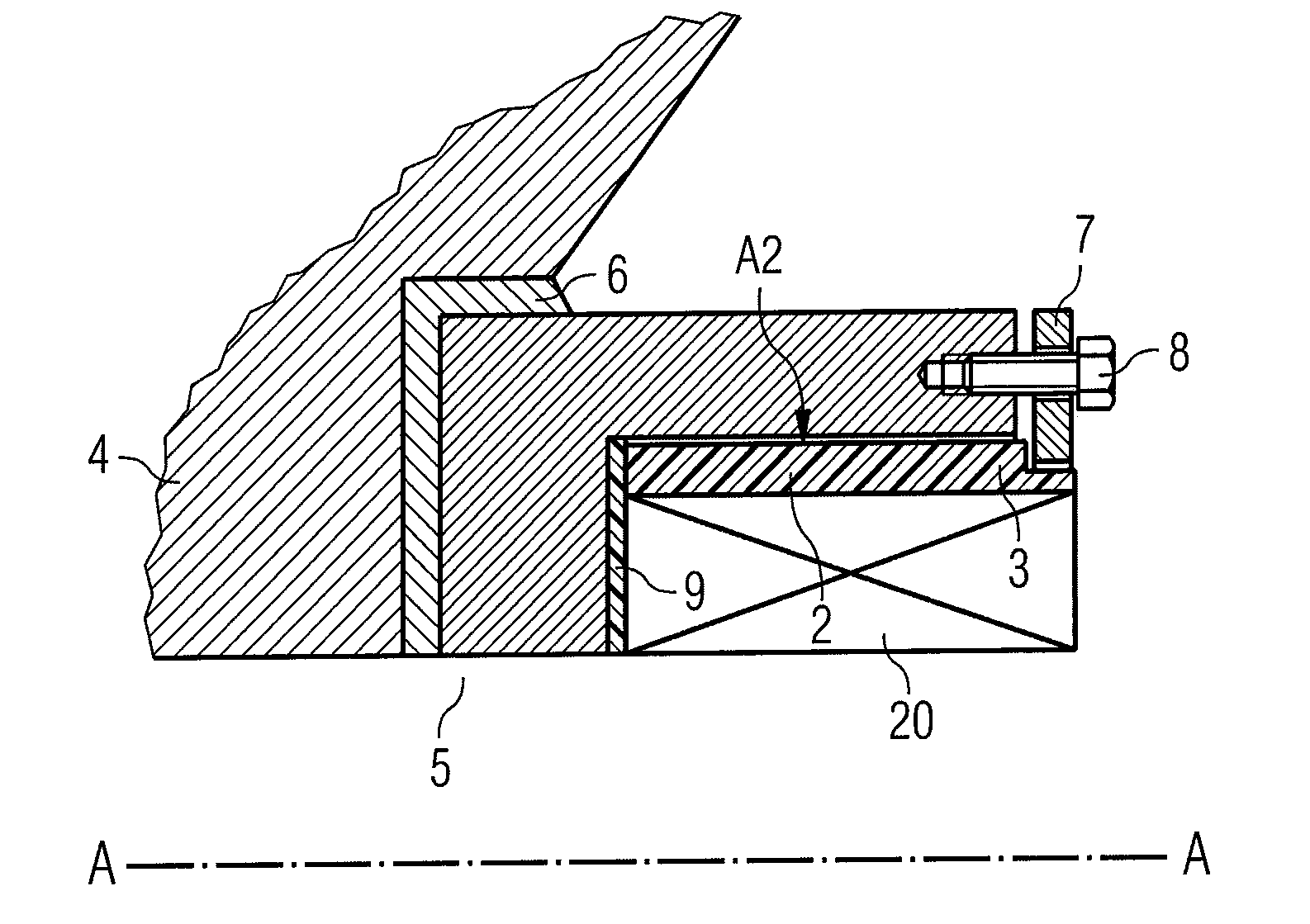
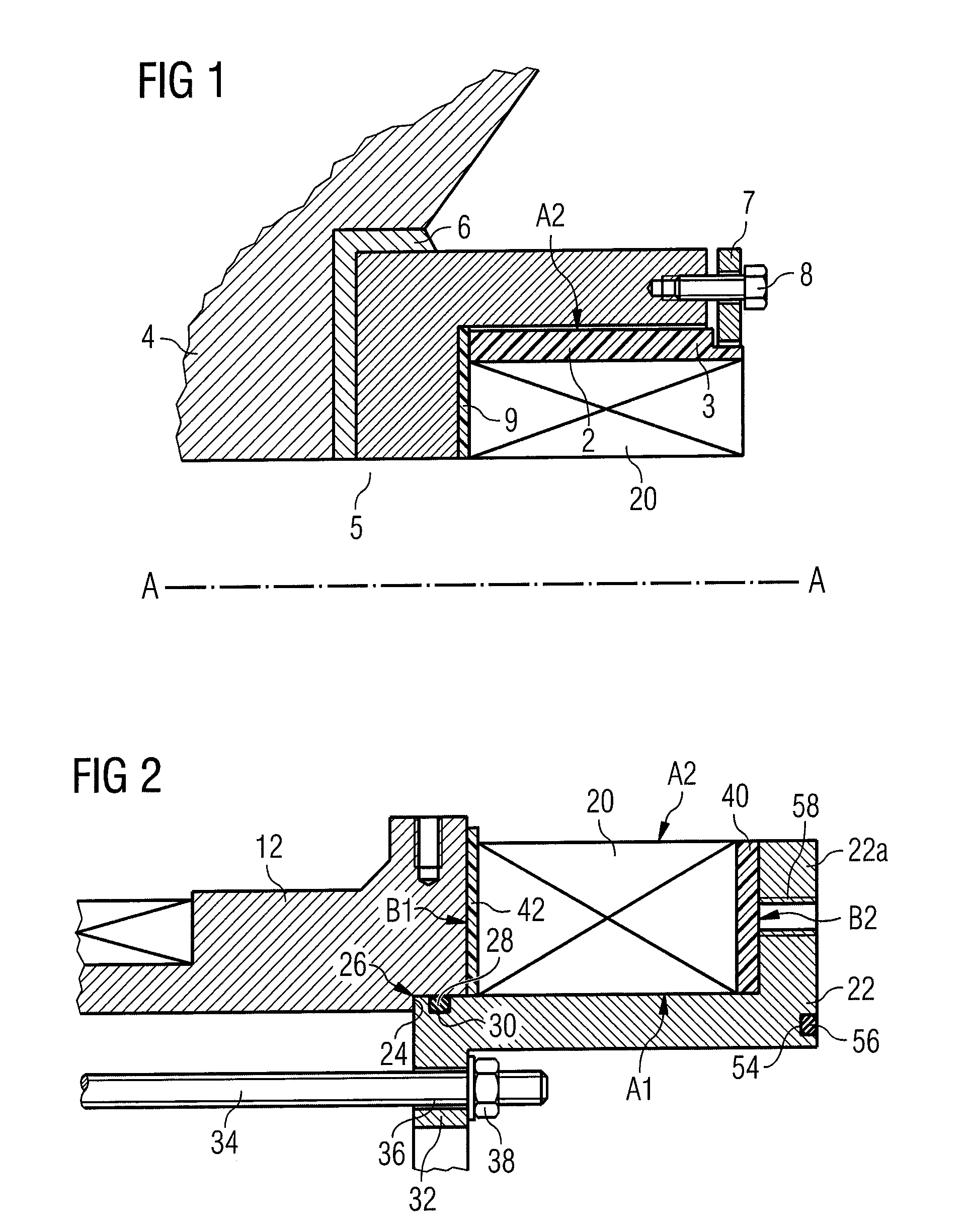
[0025]It is customary to refer to surfaces of rectangular solenoidal coils as follows. The radially inner and outer surfaces, and radii, are referred to as A1 and A2, respectively. The axially inner and outer surfaces, and positions, are referred to as B1 and B2, respectively. These labels are marked on the appropriate faces of end coil 20 in FIG. 2.

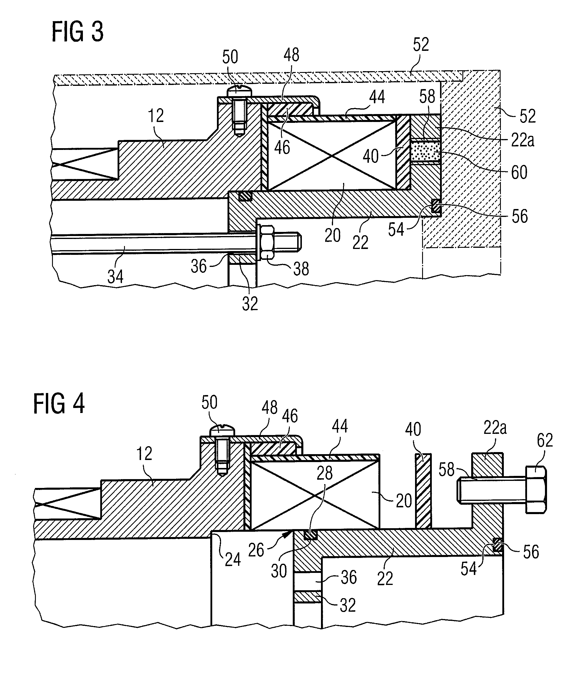
[0026]As shown in FIG. 2, the present invention provides for end coil 20 to be wound into a temporary mould 22. Preferably, this temporary mould is a single-piece annular temporary mould. This may be achieved by ensuring that the mould may simply be slid away from the former when moulding is finished, by having no raised portions axially closer to the former than the retaining wall 22a for retaining the coil to be wound. In order to achieve the wire consumption reduction and length reduction benefits of moulded end coils, there is no former material under the end coil 20 or on its B2 face when complete...


PUM

PropertyMeasurementUnit
Forceaaaaaaaaaa
Radiusaaaaaaaaaa
Circumferenceaaaaaaaaaa

Abstract

A method for manufacturing a solenoidal magnet having one or more coils wound onto a cylindrical former, and an annular end coil (20), mounted onto an end of the former such that no part of the former is present on the radially inner (A1) or axially outer (B2) sides of the end coil. The method comprises the steps of: (a) locating a temporary annular mould (22) on the end of the former; (b) retaining (32, 34, 36, 38) the temporary mould in position on the end of the former; (c) providing an interface release material (42) on an end surface of the former, exposed to the interior of the temporary mould; (d) winding wire to form the end coil into the cavity formed by the interior of the mould and the an interface release material (42) on the end surface of the former; (e) providing a step feature (46) over an axially inner part of a radially outer surface of the end coil; (f) providing a retaining strip (48), extending from the former over a radially outer surface of the step feature, and at least partially over an axially outer surface of the step feature, said retaining strip being held onto the former by retaining means (50), so as to retain the step feature in axial compression; (g) impregnating the end coil and the step feature with a hardening liquid impregnating material; and (h) once the impregnating material has hardened, removing the temporary annular mould.

Description

[0001]The present invention relates to the production of magnet coils. It particularly relates to the production of end coils for solenoidal magnets. In preferred embodiments, it relates to the production of end coils for superconducting magnets used in imaging systems such as nuclear magnetic resonance (NMR) or magnetic resonance imaging (MRI).BACKGROUND OF THE INVENTION[0002]It is conventional to manufacture solenoidal magnet coils, such as used in imaging systems such as nuclear magnetic resonance (NMR) or magnetic resonance imaging (MRI) by winding wire “in situ” into slots formed in a machined former. It is also known that a required field homogeneity may be more readily achieved by producing end coils of lesser diameter than the diameter of coils located towards the centre of the solenoidal arrangement.[0003]Such arrangements have been achieved by having a former with slots of appropriate position and diameter to locate and retain such coils. However, particularly in the field...

Claims


Application Information

Patent Timeline
IPC IPC(8): B65H18/00B21F3/00
CPCG01R33/3802G01R33/3806H01F41/048H01F6/00G01R33/3815H01F6/06
Inventor CALVERT, SIMON JAMES
Owner SIEMENS HEALTHCARE LTD
Learn More