Working distance and alignment sensor for a fundus camera

a technology of alignment sensor and fundus camera, which is applied in the field of fundus camera for retina imaging, can solve the problems of not always correct working distance determined by the approach, only working approach, and flash light,

Inactive Publication Date: 2008-07-10
CLARITY MEDICAL SYST
View PDF8 Cites 49 Cited by
  • Summary
  • Abstract
  • Description
  • Claims
  • Application Information

AI Technical Summary

Problems solved by technology

This undesirable mixing can result in the appearance of flair light, artifact, haze or ghost images on the retina image.
A major problem associated with this approach is that the working distance determined by the approach is not always correct and is highly dependent on the surface profile and orientation of the cornea surface at the light intersection point.
In other words, this approach will only work if the cornea surface that intersects with the light beam for working distance detection is not ...

Method used


Image

  • Working distance and alignment sensor for a fundus camera
  • Working distance and alignment sensor for a fundus camera
  • Working distance and alignment sensor for a fundus camera

Examples


Embodiment Construction

Overview

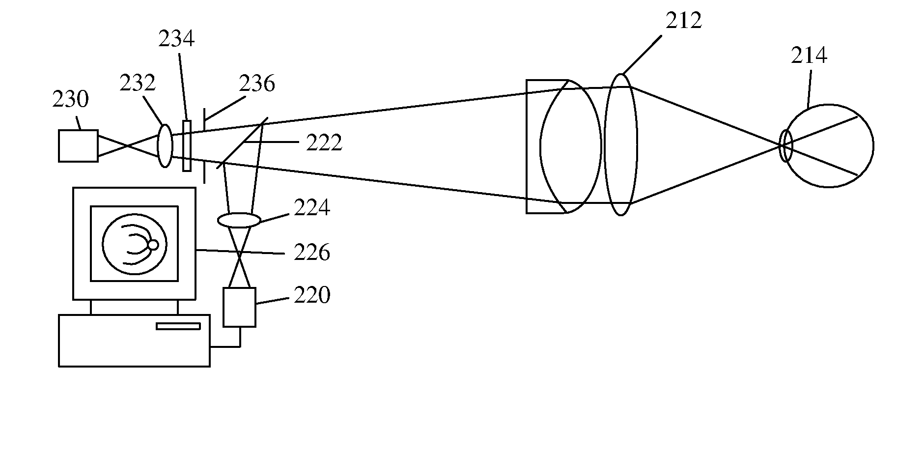
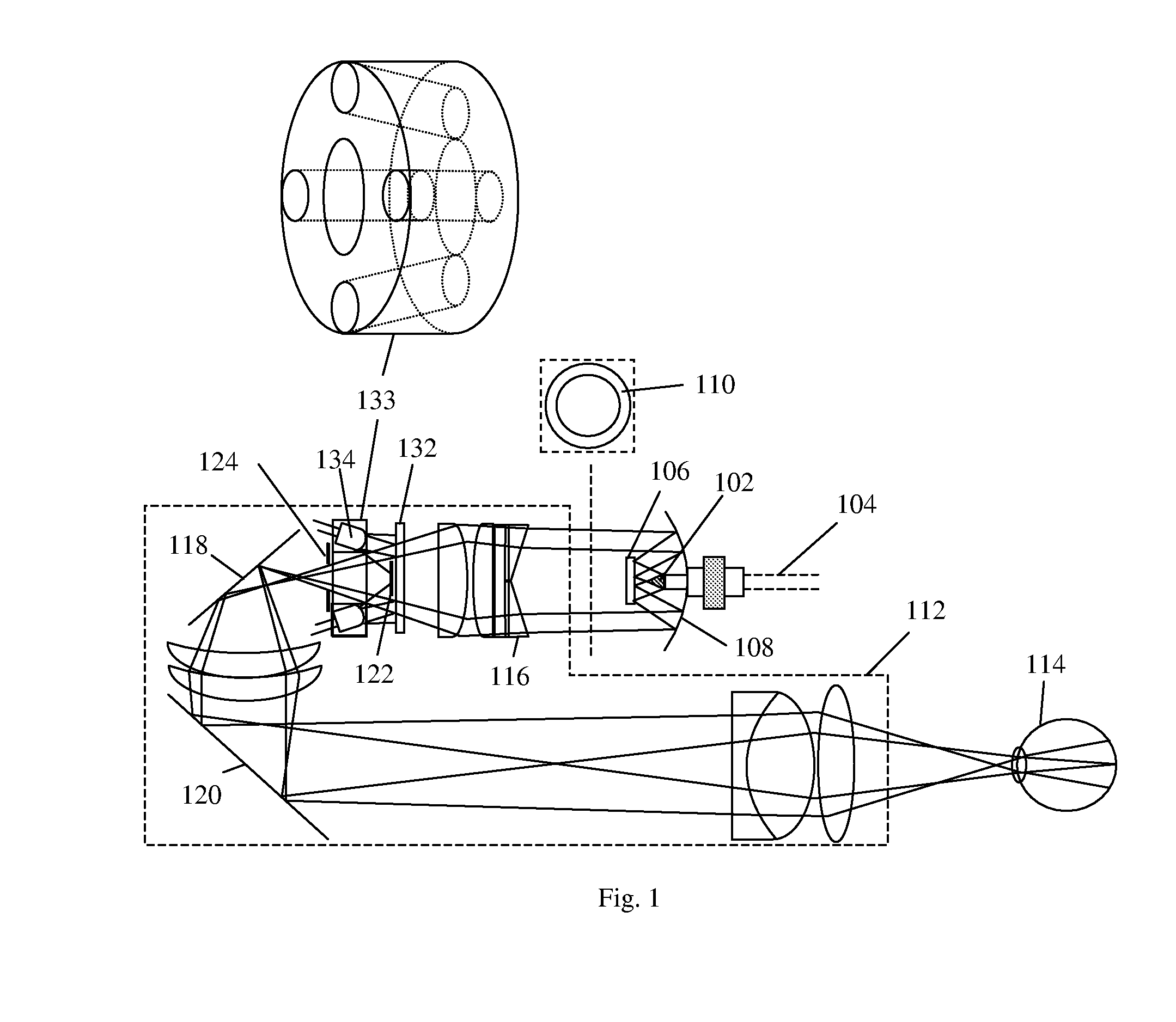
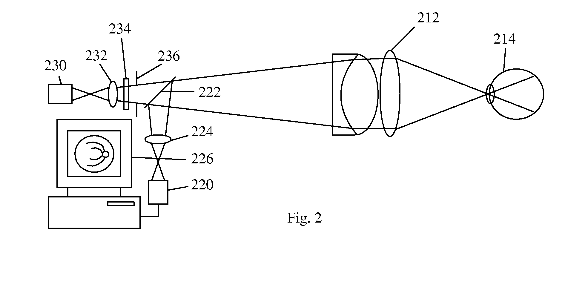
[0020]Various embodiments of the invention will be described where one embodiment is an optical arrangement of a working distance sensor in a fundus camera (note that the word fundus and retina are used interchangeably), and the associated method, in which one or more near infrared light sources such as a number of LEDs (light emitting diodes) are arranged to project a number of near infrared illumination beams into the visible light illumination path of the fundus camera. The near infrared beams may or may not substantially overlap with the visible illumination beam.

[0021]Due to the fact that the iris will generally not constrict when illuminated by near infrared light, a live view of the retina under near infrared illumination can be captured by a near infrared image sensor and displayed on a monitor before a visible retina image is taken. This live near infrared retina image can serve two purposes. Firstly, it will enable the operator to have a live view of the retina und...


PUM


Abstract

In embodiments of optical arrangements of a working distance sensor in a fundus camera that can improve the determination of a correct working distance as well as the transverse positioning of the camera a number of near infrared light sources are arranged to project a number of near infrared illumination beams into the visible light illumination path of the fundus camera and a live view of the retina under near infrared illumination is captured and displayed on a monitor. These embodiments of optical arrangements and associated methods will enable an operator to directly determine if there is any undesirable flare or other artifact appearing within a designated region on the infrared retina view as a result of a wrong alignment of the fundus camera with respect to the eye in terms of not only the working distance but also the horizontal and vertical positions. Pattern recognition algorithms can be used to further enhance the positioning sensitivity of the working distance sensor. An additional iris alignment sensor can be added to achieve a coarse alignment and also function as a measure to determine if the dilation of the iris size is sufficient for different mode of fundus imaging.

Description

TECHNICAL FIELD[0001]One or more embodiments relate to a fundus camera for retina imaging. In particular, they relate to a fundus camera with a working distance detecting means so that the captured retina image is free from undesirable flair, artifact or ghost images.BACKGROUND OF THE INVENTION[0002]When imaging the retina (or fundus, these terms will be used interchangeably) of an eye, some of the illumination light beam from a light source may be reflected and / or scattered from the cornea, the iris and the crystalline lens of the eye. It is possible that this undesired reflected and / or scattered light resulting from the interaction of the illumination light beam with the anterior segment of the eye can be mixed with the imaging beam which comprises desired light reflected / scattered from the retina of the eye for photographic imaging or observational purposes. This undesirable mixing can result in the appearance of flair light, artifact, haze or ghost images on the retina image.[00...

Claims


Application Information

Patent Timeline
IPC IPC(8): A61B3/12
CPCA61B3/12A61B3/102A61B3/152
Inventor SU, WEIZHOU, YANZHAO, QING CHUNCHENG, YEOU-YEN
Owner CLARITY MEDICAL SYST
Why Eureka
Try Eureka