
LED lamp with heat distribution capability

Inactive Publication Date: 2008-07-10
SHIAU WEN CHIN
View PDF6 Cites 36 Cited by
  • Summary
  • Abstract
  • Description
  • Claims
  • Application Information

AI Technical Summary

Benefits of technology

[0007]Therefore, the object of the present invention is to provide a LED lamp with heat distribution capability to avoid component damage due to high heat concentration.

Problems solved by technology

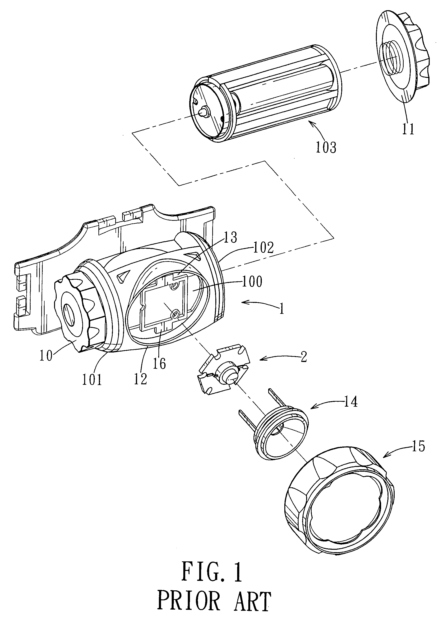
However, since the housing 1, the supporting plates 13, the positioning seat 16, the reflector 14, and the lamp cap 15 are all made from plastic, highly concentrated heat generated by the light emitting diode unit 2 is likely to cause damage to these components, thereby resulting in a relatively short service life for the conventional LED lamp.

Method used


Image

  • LED lamp with heat distribution capability
  • LED lamp with heat distribution capability
  • LED lamp with heat distribution capability

Examples


Embodiment Construction

[0013]Before the present invention is described in greater detail, it should be noted that like elements are denoted by the same reference numerals throughout the disclosure.

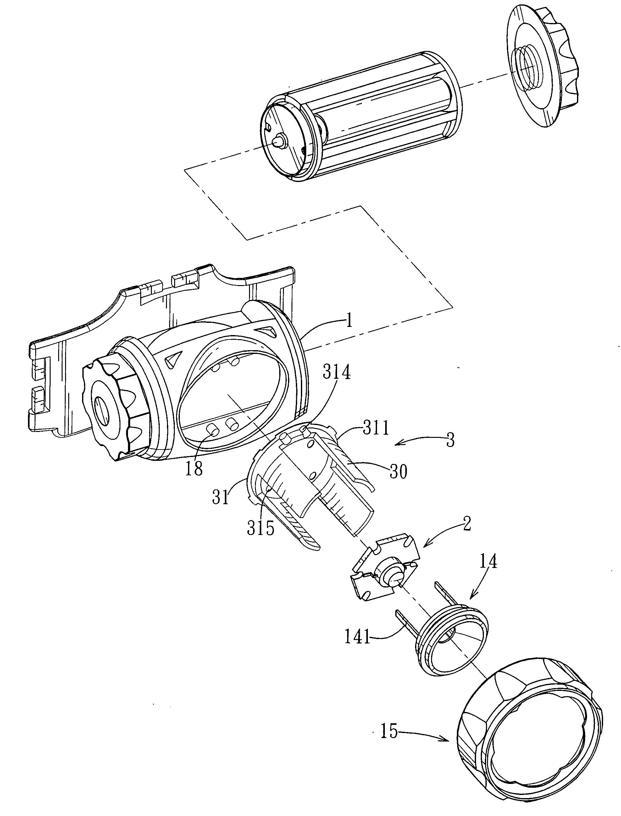
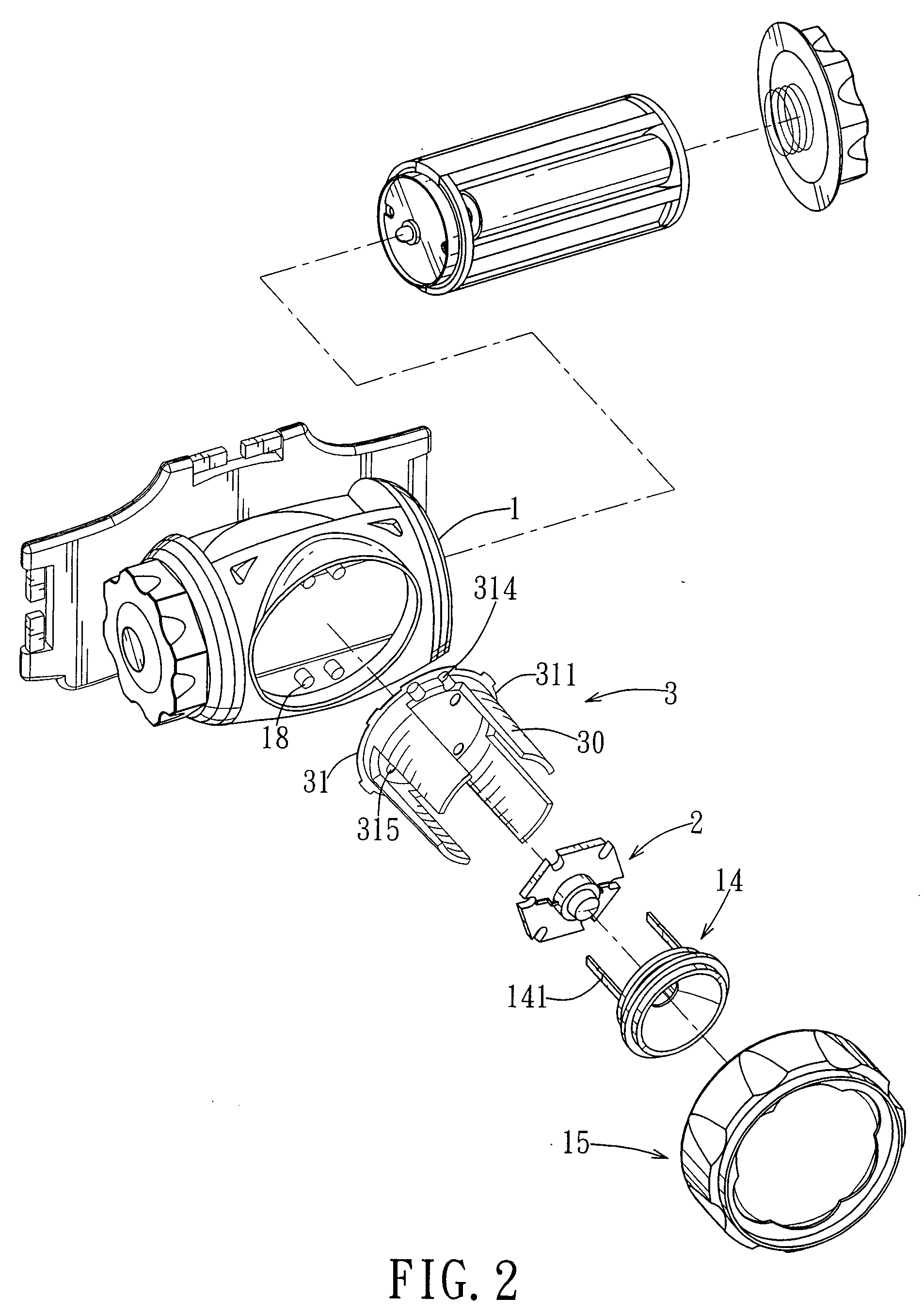
[0014]As shown in FIG. 2, the preferred embodiment of a LED lamp according to the present invention comprises a housing 1, a heat conducting member 3 including a base plate 31 that is mounted on the housing 1, that has one side opposite to the housing 1, and that has a peripheral portion 311, and a high wattage light emitting diode unit 2 mounted on the side of the base plate 31. The heat conducting member 3 further includes four curved heat conducting fins 30 that extend from the peripheral portion 311 of the base plate 31 away from the housing 1, that are angularly spaced apart from each other, and that surround the light emitting diode unit 2. The heat conducting member 3 is made of a highly thermally conductive material.

[0015]The preferred embodiment further comprises a reflector 14 mounted to the heat condu...


PUM


Abstract

A light emitting diode (LED) lamp includes a housing, and a heat conducting member made of a highly thermally conductive material. The heat conducting member includes a base plate that is mounted on the housing and that has one side opposite to the housing, and at least one heat conducting fin extending from the base plate away from the housing. The LED lamp further includes a light emitting diode unit mounted on the side of the base plate.

Description

CROSS-REFERENCE TO RELATED APPLICATION[0001]This application claims priority of Taiwanese Application No. 096100309, filed on Jan. 4, 2007.BACKGROUND OF THE INVENTION[0002]1. Field of the Invention[0003]The invention relates to a light emitting diode (LED) lamp, more particularly to a LED lamp with heat distribution capability.[0004]2. Description of the Related Art[0005]As shown in FIG. 1, a conventional LED lamp, such as a head lamp or a flashlight, includes a housing 1 that has first and second end portions 101, 102. A power switch 10 is disposed at the first end portion 101, and a cover 11 is coupled to the housing 1 at the second end portion 102. The housing 1 confines a receiving space 100 between the first and second end portions 101 and 102 for receiving a battery set 103. The housing 1 is formed with an opening 12 between the first and second end portions 101 and 102, and further has a pair of supporting plates 13 extending across the opening 12. The housing 1 further inclu...

Claims


Application Information

Patent Timeline
IPC IPC(8): F21V29/00
CPCF21V29/004F21V29/74F21Y2101/02F21Y2115/10F21V29/763
Inventor SHIAU, WEN-CHIN
Owner SHIAU WEN CHIN
Learn More