Spiral drill bit and method of forming same

a drill bit and spiral technology, applied in the field of spiral drill bits, can solve the problems of wasting time and money in the field, reducing requiring a considerable amount of force to grind all three types of clearances onto the step drill bit, so as to reduce the time and cost of forming the spiral drill bit, reduce the amount of grinding, and reduce the effect of cutting the workpi

Active Publication Date: 2008-07-10
GREENLEE TEXTRON
View PDF3 Cites 39 Cited by
  • Summary
  • Abstract
  • Description
  • Claims
  • Application Information

AI Technical Summary

Benefits of technology

[0011]Briefly, the present invention discloses a spiral drill bit which provides a plurality of cutting surfaces with different diameters and therefore allows holes of varying sizes to be cut with the spiral drill bit. Proper radial, axial and diametral

Problems solved by technology

This, of course, saves time and money in the field.
Commonly, step drill bits, such as the one shown in FIGS. 1-3, are formed by first turning the general profile of the step bit and then grinding the necessary axial, diametral, and radial clearances A, B, C. A disadvantage of this technique is that a considerable amount of force is necessary to grind all three

Method used


Image

  • Spiral drill bit and method of forming same
  • Spiral drill bit and method of forming same
  • Spiral drill bit and method of forming same

Examples


Embodiment Construction

[0023]While the invention may be susceptible to embodiment in different forms, there is shown in the drawings, and herein will be described in detail, a specific embodiment with the understanding that the present disclosure is to be considered an exemplification of the principles of the invention, and is not intended to limit the invention to that as illustrated and described herein.

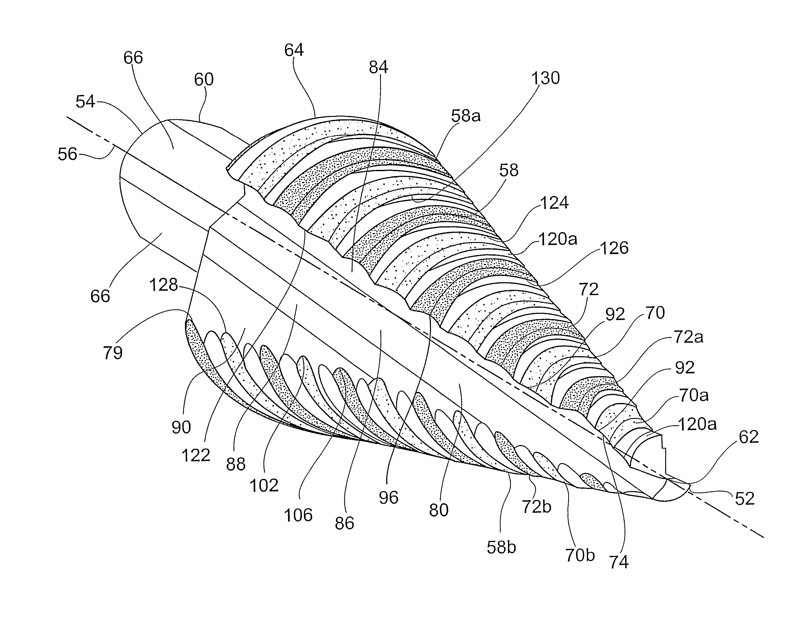
[0024]As best illustrated in FIGS. 4 and 5, a spiral drill bit 50 includes a generally conically-shaped main body 58 extending from a tip 62 at a front end 52 to a rear wall 64, and a shank 60 extending from the rear wall 64 of the main body 58. The tip 62 provides a split drill point. The end of the shank 60 defines a rear end 54. A central axis 56 extends from the front end 52 to the rear end 54. The rear wall 64 is perpendicular to the central axis 56. Flats 66 are provided on the shank 60 and provide driving surfaces for rotation of the spiral drill bit 50 when mounted within the chuck of an associat...


PUM

PropertyMeasurementUnit
Angleaaaaaaaaaa
Angleaaaaaaaaaa
Angleaaaaaaaaaa

Abstract

A spiral drill bit for forming holes of a variety of sizes has a main body which provides first and second helical grooves. First and second flutes extend along the length of the main body to provide first and second helical groove segments. Cutting segments are provided between the helical groove segments. The method for forming the spiral drill bit includes turning the helical groove segments onto a round stock. An axial clearance and an initial diametral clearance are provided upon turning the helical grooves. A grinding process is used to form a radial clearance and a final diametral clearance. The reduction to the amount of grinding required to form the spiral drill bit results in a reduction to the cost of production and a reduction in the time necessary to produce the spiral drill bit.

Description

[0001]This application claims the domestic benefit of U.S. Provisional Application Ser. No. 60 / 878,846 filed on Jan. 5, 2007, which disclosure is hereby incorporated by reference.FIELD OF THE INVENTION[0002]This invention is generally directed to a spiral drill bit for forming holes having different diameters and the method for forming the spiral drill bit.BACKGROUND OF THE INVENTION[0003]For a number of years, step drill bits have been commonly used, for example in the electrical industry, for cutting holes in panels made of sheet metal. One of the advantages that these step bits provide is that they can be used to cut a variety of holes of different diameters without requiring different drill bits to be mounted to and dismounted from a chuck of a powered tool. This, of course, saves time and money in the field.[0004]A conventional step drill bit 10 is shown in FIGS. 1-4. For the purposes of reference and ease of discussion, the end 12 of the drill bit 10 which first contacts the w...

Claims


Application Information

Patent Timeline
IPC IPC(8): B23B51/02B21K5/04
CPCB23B51/009B23P15/28Y10T408/906B24B19/04B23P15/32
Inventor GENTRY, CHARLES L.NORDLIN, WILLIAM F.
Owner GREENLEE TEXTRON
Why Eureka
Try Eureka