Tunable contact angle process for immersionlithography topcoats and photoresists

a technology of immersion lithography and contact angle, which is applied in the field of immersion lithography, can solve the problems of affecting the unmasked photoresist, affecting the effect of the masked photoresist, and requiring significant re-engineering for submerging significant portions of multi-million dollar equipment, etc., and achieves the effect of maintaining a bubble-free even layer of water between the moving lens and the wafer, and achieving the effect of reducing

Active Publication Date: 2008-07-10
IBM CORP
View PDF20 Cites 20 Cited by
  • Summary
  • Abstract
  • Description
  • Claims
  • Application Information

AI Technical Summary

Benefits of technology

[0015]A further embodiment of the invention includes a surface modification process for an immersion photoresist including coating a photoresist layer onto a

Problems solved by technology

As the projected light hits the photoresist on the silicon wafer, it may alter the unmasked photoresist.
A number of practical issues to implementing immersion lithography exist.
An issue with this approach is that submerging significant portions of multi-million dollar equipment requires significant re-engineering.
Continuously maintaining a bubble-free even layer of water between the moving lens and wafer can be quite difficult using this technique, and larger topographical discontinuities, such as workpiece edges, complicate the engineering.
Even where immersion lithography has been shown to be a somewhat effective and simple enhancement technique to extend the limits of optical lithography, the contact between the immersion fluid and the resist could potentially lead to partial resist image degradation.
All practiced methods used to manage the immersion fluid during the exposure step cannot perfectly contain the water within the scanner showerhead, and

Method used


Image

  • Tunable contact angle process for immersionlithography topcoats and photoresists
  • Tunable contact angle process for immersionlithography topcoats and photoresists
  • Tunable contact angle process for immersionlithography topcoats and photoresists

Examples


examples 1-8

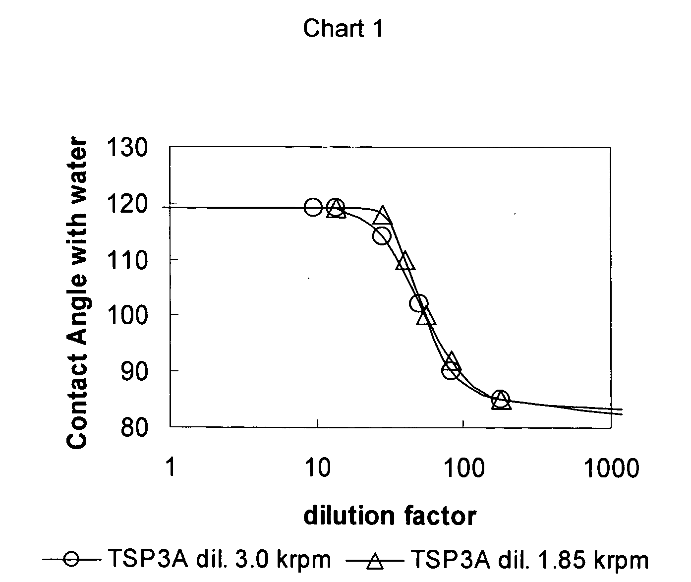
[0032]A substrate was coated with a photoresist layer and a standard immersion topcoat material. A fluorinated polymer layer was applied to the top of the standard immersion topcoat material layer via spin coating. The fluorinated polymer was TSP3A, which was diluted by perfluoro-2-butyltetrahydrofuran in various dilution percentages as set forth in Table 1 below. Further, for the examples the spin speed combinations were varied as set forth in Table 1 below. Advancing contact angle values of the fluorinated polymer layer were determined as well as solubility in TMAH and are included in Table 1 below.

TABLE 1Dilution (diluter(g) / Advancingfluorinated polymer orSpin speedcontactSoluble informulation(g))(krpm)angleTMAHExample 11:103119NoExample 21:143119Slow -YesExample 31:281.85118YesExample 41:411.85110YesExample 51:501.85100YesExample 61:831.8592YesExample 7 1:1831.8585YesExample 8 1:10001.8582Yes

[0033]Chart 1 below is a representation of Table 1 above wherein the x-axis is various d...

examples 9-17

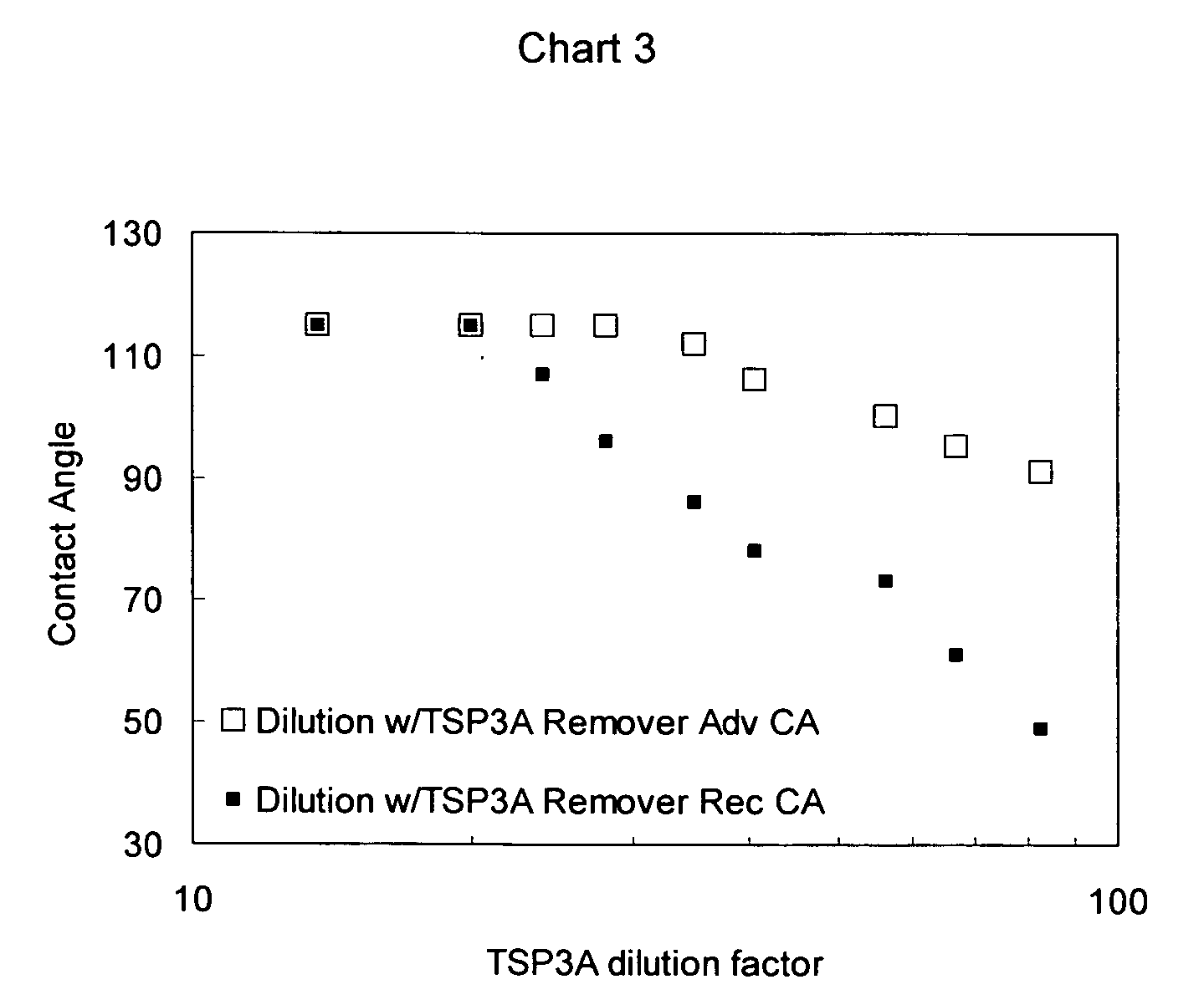
[0035]A substrate was coated with a photoresist layer and a standard immersion topcoat material. A fluorinated polymer layer was applied to the top of a standard immersion topcoat material layer via spin coating at 1.85 krpm. The fluorinated polymer was TSP3A which was diluted by perfluoro-2-butyltetrahydrofuran in various dilution percentages as set forth in Table 2 below. Advancing and receding contact angle values of the fluorinated polymer layer were determined and are included in Table 2 below.

TABLE 2AdvancingRecedingDilutionContact Anglecontact angleExample 91:14115115Example 1020115115Example 1124115107Example 122811596Example 133511286Example 144310678Example 155010073Example 16679561Example 17839149Standard - neat7065immersion topcoatsurface (PNBHFA)Standard - neat6545–25immersion topcoatsurface(PMVEMA4Me2Pe)

[0036]Chart 3 below is a representation of advancing and receding contact angles for neat immersion surfaces.

examples 18-31

[0037]A substrate was coated with a photoresist layer and a standard immersion topcoat material. A fluorinated polymer layer was applied to the top of a standard immersion topcoat material layer via spin coating at 1.85 krpm. The fluorinated polymer was CYTOP® (a formulation containing a fluorinated polymer (Poly(1,1,2,4,4,5,5,6,7,7-decafluoro-3-oxa-1,6-heptadiene) in perfluorotributylamine) which was diluted by a perfluorohydrocarbon (Fluorinert™ Fluid FC-77) in various dilution percentages as set forth in Table 3 below. Advancing and receding contact angle values of the fluorinated polymer layer were determined and are included in Table 3 below.

TABLE 3Advancing ContactDilutionAngleExample 181118Example 190.5118Example 200.2117Example 210.15117Example 220.125117Example 230.12117Example 240.115117Example 250.11103Example 260.1100Example 270.1100Example 280.0594Example 290.0190Example 300.00190Example 310.000190

[0038]Chart 4 below is a representation of Table 3 above wherein the x-ax...


PUM


Abstract

A process for tuning the water contact angle of an immersion photoresist layer or immersion topcoat layer by modification of the top surface. The surface modification is a layer of fluorinated polymer.

Description

FIELD OF THE INVENTION[0001]The invention generally relates to immersion lithography for semiconductor fabrication and, more particularly, to a process for surface modification of a photoresist layer and / or topcoat.BACKGROUND OF INVENTION[0002]Lithography is used in semiconductor fabrication via radiation to transfer images onto a substrate coated with a material reactive to the radiation. Radiation in the form of light, for example, ultraviolet light, may be directed onto a mask (i.e., a photomask) defining a pattern. After shining through or reflecting from a mask the light is projected through a series of optical lenses and / or mirrors that shrink the image. The reduced image is then projected onto the workpiece. The workpiece may, for example, be silicon or other semiconductor wafer covered with a radiation-sensitive photoresist. As the projected light hits the photoresist on the silicon wafer, it may alter the unmasked photoresist. Unaltered photoresist may then be chemically wa...

Claims


Application Information

Patent Timeline
IPC IPC(8): G03C5/00
CPCG03F7/0046G03F7/2041G03F7/11
Inventor GOLDFARB, DARIO LEONARDO
Owner IBM CORP
Why Eureka
Try Eureka