
Flexible cable for optical disk drive

Inactive Publication Date: 2008-07-10
QUANTA STORAGE INC
View PDF6 Cites 1 Cited by
  • Summary
  • Abstract
  • Description
  • Claims
  • Application Information

AI Technical Summary

Benefits of technology

[0008]It is therefore an object of the invention to provide a flexible cable for an optical disk drive, and an intensive area of the flexible cable is disposed at a beginning end of a moving part in capable of supporting the flexible cable with elasticity. It reduces the load of the flexible cable and preventing the flexible cable from harm.
[0009]It is therefore another object of the invention to provide a flexible cable for an optical disk drive, wherein a smooth layer is disposed at where the case and the moving part of the flexible cable connect, for reducing the resisting force generated from the tray pushing backwards and decreasing the attrition.

Problems solved by technology

Thus, whether the flexible cable moving backwards and forwards can transmit signal stably affects the reliability of the optical disk drive.
Thus, the flexible cable 14 is attrite and incapable of transmitting signal normally.
However, the flexible cable 14 droops more easily because the total weight of the flexible cable 14 to which the intensive area 143 is added increases while its elasticity is not strong enough.
Therefore, the problems of the conventional flexible cable for an optical disk drive still exist and need to be solved.

Method used


Image

  • Flexible cable for optical disk drive
  • Flexible cable for optical disk drive
  • Flexible cable for optical disk drive

Examples


Embodiment Construction

[0018]In order to achieve the purpose mentioned above, two embodiments are detailed described below. The invention will become apparent from the following detailed description of the preferred but non-limiting embodiments. The following description is made with reference to the accompanying drawings.

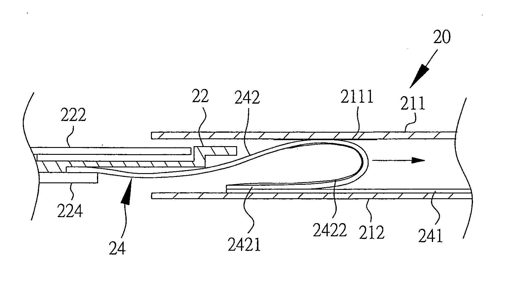
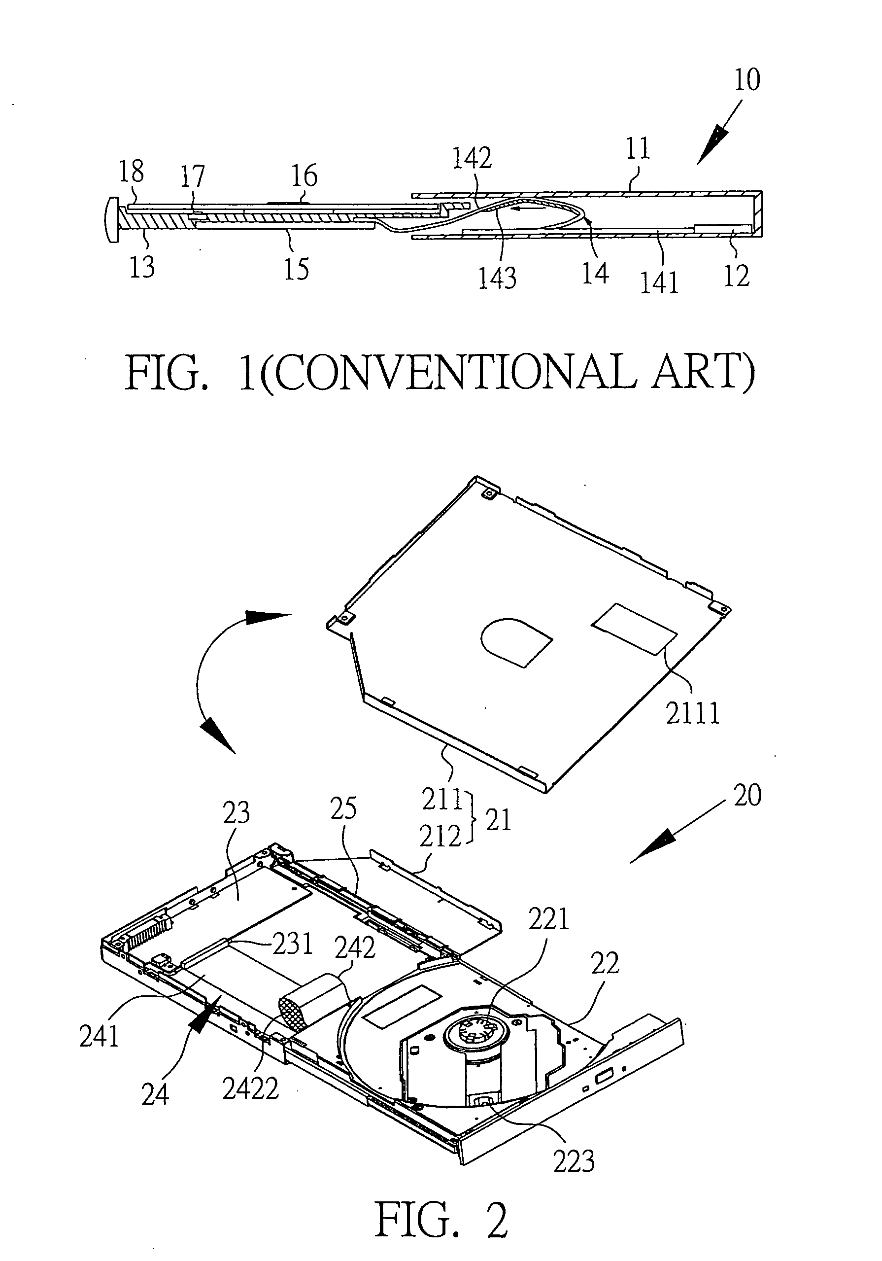
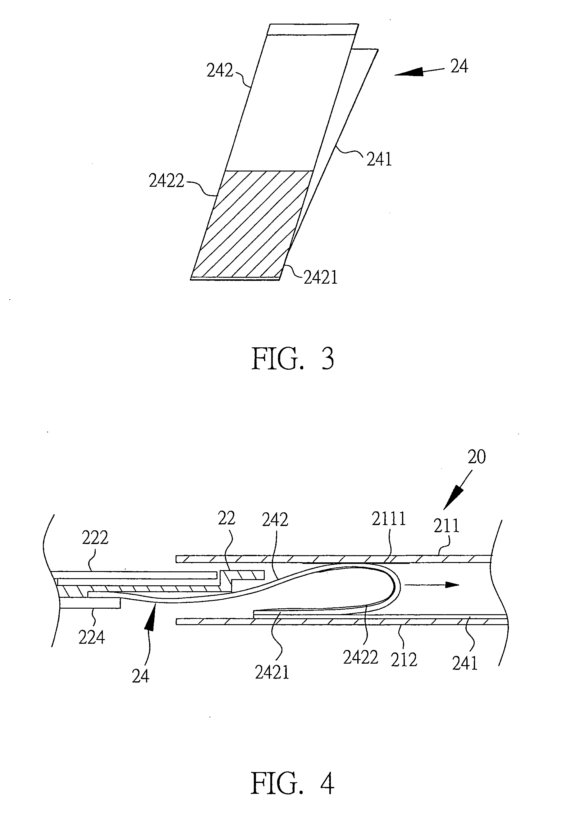
[0019]Referring to FIG. 2, a schematic view of a flexible cable for an optical disk drive 20 according to a first embodiment of the present invention is shown. The optical disk drive 20 comprises a case 21, a tray 22, a main board 23, and a flexible cable 24. The case 21 is hollow, and it allows the tray 22 to slide into and out of the case 21. One end of the flexible cable 24 is connected to the rear end of the tray 22, and the other end of the flexible cable 24 is connected to the main board 23 located at the rear end of the case 21. Thus, the flexible cable 24 still can transmit signal when the tray 22 moves relatively to the case 23.

[0020]The case 21 comprises an upper case 211 and a...


PUM


Abstract

A flexible cable for an optical disk drive is disposed at a case comprising an upper case and a lower case. The flexible cable comprises a fastening part fixed at the lower case and a moving part extended in the reverse direction of one end of the fastening part to form a beginning end fixed at the case. An intensive area comprised of elastic material is disposed at the surface of the beginning end and nearby the beginning end of the moving part. A smooth layer is disposed at the inside of the upper case and located on the moving path of the intensive area disposed at the moving part to be touched by the intensive area when the moving part is bent reversely. A secondary intensive area is disposed at the moving part, and is extended or separated from the intensive area, to prevent the flexible cable drooping.

Description

BACKGROUND OF THE INVENTION[0001]1. Field of the Invention[0002]The invention relates in general to an optical disk drive, and more particularly to a flexible cable connecting a tray and a main board in the optical disk drive for electronically connection and data transmission.[0003]2. Description of the Related Art[0004]In general, a flexible cable is utilized for electronically connecting to a tray which is movable and a main board which is fixed in an optical disk drive, for providing the power and the data transmitting of the electronic components on the tray. Thus, whether the flexible cable moving backwards and forwards can transmit signal stably affects the reliability of the optical disk drive.[0005]Refer to FIG. 1, a schematic view of a conventional optical disk drive 10 is shown. The optical disk drive 10 comprises a hollow case 11 for accommodating a main board 12 and a tray 13. The main board 12 connects with one end of a fastening part 141 of a flexible cable 14. One en...

Claims


Application Information

Patent Timeline
IPC IPC(8): H01R3/00
CPCH01R35/02
Inventor OU, HSIEN-CHUNGCHANG, CHEN-FUYANG, LI-LI
Owner QUANTA STORAGE INC
Learn More