
Apparatus and method for cooperative transmission in multi-antenna relay wireless communication system

Active Publication Date: 2008-07-10
SAMSUNG ELECTRONICS CO LTD +1
View PDF7 Cites 84 Cited by
  • Summary
  • Abstract
  • Description
  • Claims
  • Application Information

AI Technical Summary

Problems solved by technology

However, since there is no concrete method for optimizing the covariance matrix and the relay matrix, a problem arises when the cooperative transmission is performed.

Method used


Image

  • Apparatus and method for cooperative transmission in multi-antenna relay wireless communication system
  • Apparatus and method for cooperative transmission in multi-antenna relay wireless communication system
  • Apparatus and method for cooperative transmission in multi-antenna relay wireless communication system

Examples


first embodiment

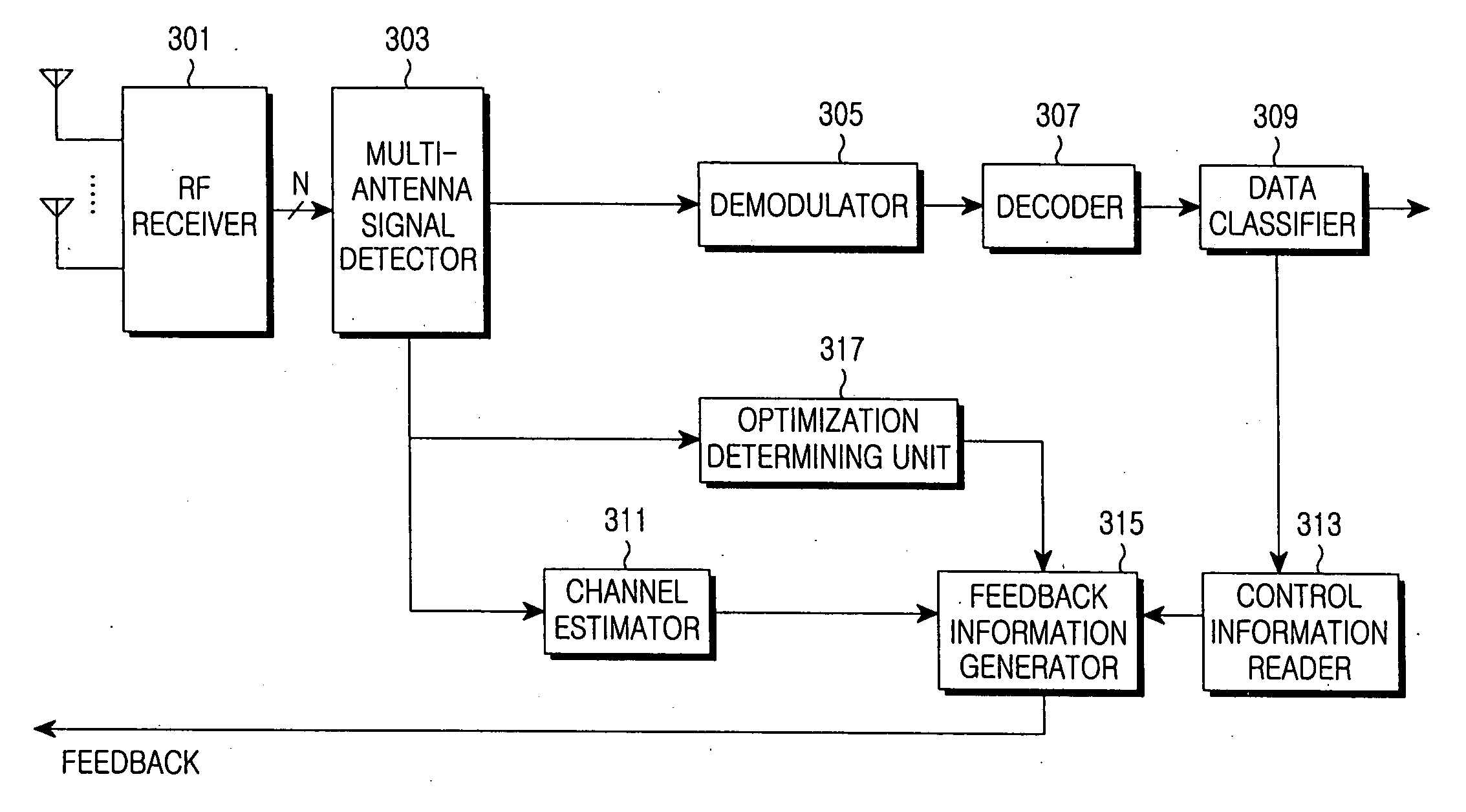
[0049]The optimization determining unit 317 determines whether the signal transmission method, that is, covariance matrices and relay matrix, is optimally configured. In other words, whenever the covariance matrices Q1 and Q2 and the relay matrix G are reconfigured the optimization determining unit 317 measures Rx signal strength, and, if an improvement value of the Rx signal strength is less than or equal to a threshold, determines that optimal configuration is achieved. For example, the Rx signal strength may be a signal to interference and noise ratio (SINR), a signal to noise ratio (SNR), or a carrier to interference and noise ratio (CINR).

[0050]Alternatively, the optimization determining unit 317 may evaluate the number of times of performing the reconfiguration in order to determine whether optimization is achieved or not. That is, in terms of statistics, under the assumption that optimization is achieved when the reconfiguration is repeated by a predetermined number of times...

second embodiment

[0090]Now, operations of all nodes will be described in detail with reference to the present invention.

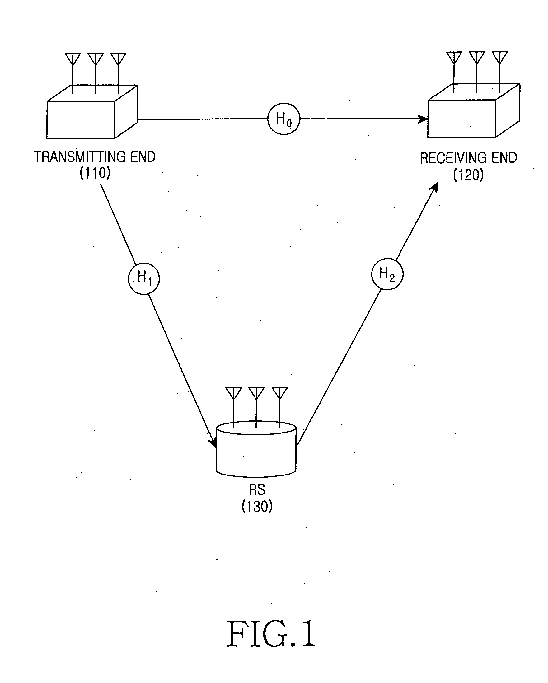
[0091]First, operations of all nodes will be described in brief with reference to FIG. 1 according to the second embodiment of the present invention. The receiving end 120 estimates the channels H0 and H2, and then receives feed forward information on the channel H1. Subsequently, the receiving end 120 selects a Tx antenna of the transmitting end 110 using the channel information, and feeds back the selection result to the transmitting end 110. In addition, the receiving end 120 feeds back information on the estimated channel H2 to the RS 130. Upon receiving the feedback of the information on the channel H2, the RS 130 determines a matching method (i.e., an antenna permutation matrix) for an Rx antenna and a Tx antenna. Thereafter, each node performs communication according to the determined antenna permutation matrix through cooperative transmission.

[0092]FIG. 8 is a flowchart ill...


PUM


Abstract

An apparatus and method for cooperative transmission in a multi-antenna relay wireless communication system are provided. A receiving end includes an estimator, a reader, a feedback unit and a detector. According to the present invention, the receiving end receives the signal from both the transmitting end and the relay station. Therefore, a reception gain is obtained and a high throughput can be ensured.

Description

CROSS-REFERENCE TO RELATED APPLICATION(S) AND CLAIM OF PRIORITY[0001]This application claims priority under 35 U.S.C. §119(a) to a Korean patent application filed in the Korean Intellectual Property Office on Jan. 9, 2007 and assigned Serial No. 2007-2341, the entire disclosure of which is hereby incorporated by reference.TECHNICAL FIELD OF THE INVENTION[0002]The present invention relates to a multi-antenna relay wireless communication system. More particularly, the present invention relates to an apparatus and method for cooperative transmission in a multi-antenna relay wireless communication system.BACKGROUND OF THE INVENTION[0003]In a next generation, or 4th Generation (4G), communication system, research is being actively conducted to provide services having various Quality of Service (QoS) requirements, for example, a throughput of about 1 Gbps when stationary and a throughput of about 100 Mbps when on the move. In particular, research on the 4 G communication systems is ongoin...

Claims


Application Information

Patent Timeline
IPC IPC(8): H04B1/00
CPCH04B7/026H04W52/46H04W52/241H04B7/0626
Inventor KIM, DONG-HOCHO, MYEON-KYUNKIM, YUNG-SOOBAR-NESS, YEHESKELSIMEONE, OSVALDOVARANESE, NICOLA
Owner SAMSUNG ELECTRONICS CO LTD
Learn More