Hinge assembly

Inactive Publication Date: 2008-07-17
SHIN ZU SHING
View PDF11 Cites 8 Cited by
  • Summary
  • Abstract
  • Description
  • Claims
  • Application Information

AI Technical Summary

Benefits of technology

[0008]The main objective of the present invention is to provide a hinge assembly

Problems solved by technology

However, since the bolts are additionally provided and are necessarily mounted along with th

Method used


Image

  • Hinge assembly
  • Hinge assembly
  • Hinge assembly

Examples


Embodiment Construction

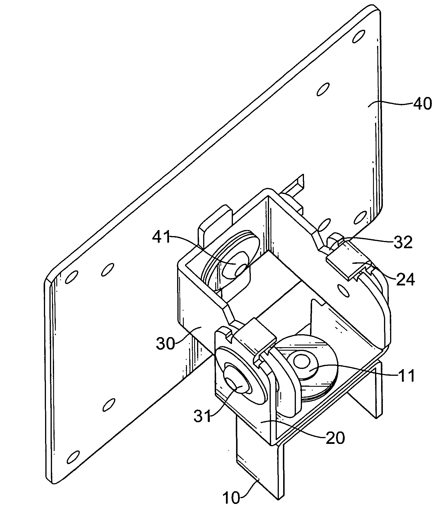
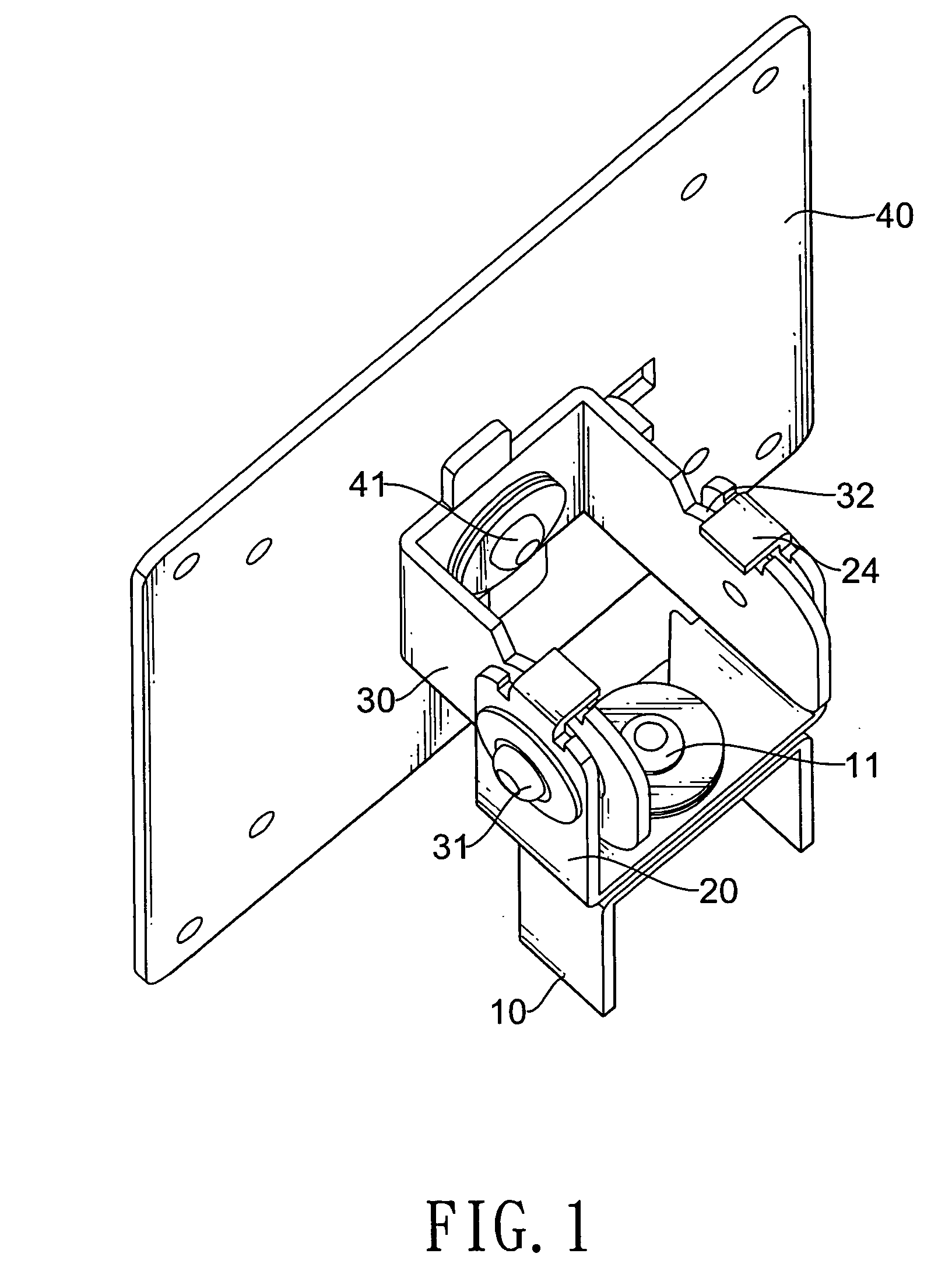
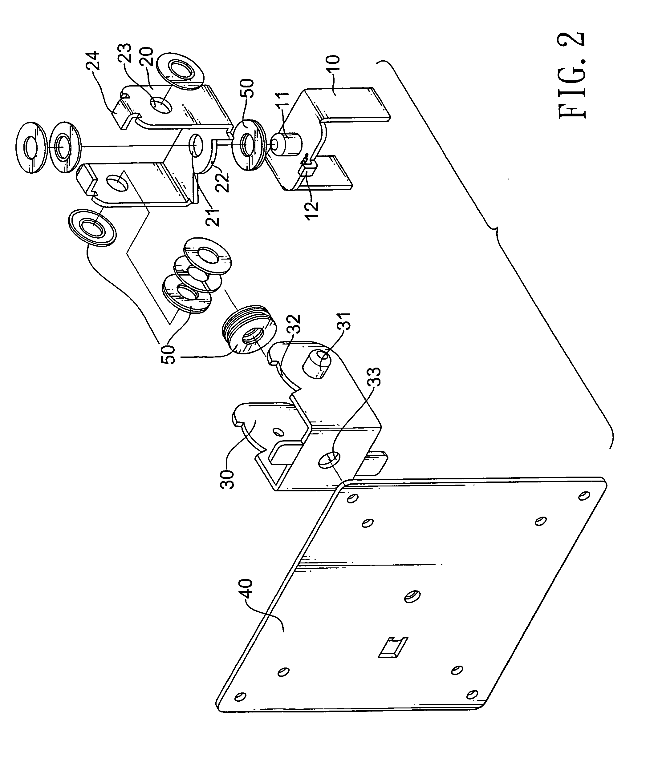
[0018]With reference to FIGS. 1 and 2, the hinge assembly in accordance with the present invention comprises a stage (10), a rotating bracket (20), a mounting bracket (30), a fixing board (40) and multiple spacing and retaining assemblies (50).

[0019]The stage (10) can be installed in a base of an electronic display and has a top, an edge, a first mounting protrusion (11) and a first limit (12). The first mounting protrusion (11) is formed on the top of the stage (10) by means of punching, pressing . . . etc. The first limit (12) is formed on the edge of the stage (10).

[0020]With further reference to FIG. 5, the rotating bracket (20) is U-shaped, is mounted rotatably on the top of the stage (10) and has a central wing and two side wings. The central wing has two ends, an inner edge, a first mounting hole (21) and a first notch (22). The first mounting hole (21) is formed through the central wing of the rotating bracket (20) and corresponds to and is mounted rotatably around the first...


PUM


Abstract

A hinge assembly has multiple components that have mounting holes and mounting protrusions respectively. The mounting protrusions are formed on the components and correspond to and are mounted rotatably in the mounting holes respectively. Such that the hinge assembly is assembled without any additional connecting elements like bolts and fabrication of the hinge assembly may be convenient and low-cost.

Description

BACKGROUND OF THE INVENTION[0001]1. Field of the Invention[0002]The present invention relates to a hinge, and more particularly to a hinge assembly that is convenient and low-cost to fabricate.[0003]2. Description of Related Art[0004]An electronic display such as a LCD or a computer monitor generally comprises a base, a panel and a hinge assembly. The hinge assembly is typically mounted between the panel and the base to make the panel rotatable relative to the base for convenience of watching the panel.[0005]Mostly, the conventional hinge assembly comprises multiple components that have multiple mounting holes and multiple bolts. The mounting holes are formed through the components and correspond to each other respectively. The bolts extend though and mounted pivotally in the corresponding mounting holes. With such an arrangement, the conventional hinge assembly is rotatable to adjust the visual angle or orientation of the panel and facilitate watching.[0006]However, since the bolts...

Claims


Application Information

Patent Timeline
IPC IPC(8): E05D5/02E05D11/10
CPCE05D3/10E05Y2900/606F16M11/10Y10T16/54H04M1/0214Y10T16/554F16M11/2021
Inventor HSU, CHUN-CHING
Owner SHIN ZU SHING
Why Eureka
Try Eureka