Shear connector for corrugated sheet steel and concrete

a technology of corrugated sheet steel and connectors, applied in the direction of bridges, basic electric elements, bridge structural details, etc., to achieve the effect of easy production, increased shear resistance performance, and large area

Active Publication Date: 2016-09-20
JIANGSU TRANSPORTATION RES INST CO LTD
View PDF18 Cites 1 Cited by
  • Summary
  • Abstract
  • Description
  • Claims
  • Application Information

AI Technical Summary

Benefits of technology

[0006]The purpose of this invention is to provide a connector for corrugated sheet steel and concrete, and this connector can ensure effective transfer of the horizontal shear force occurring between the steel and concrete materials, with sufficient shear strength for the shear parts, and can also be conveniently fabricated and used in construction works.
[0008]In this invention, U-shaped steel channel is used, as it has two vertical walls, compared with L-shaped steel, it can provide larger area to resist the horizontal shear load in the longitudinal direction of the bridge, to increase the shear resistant performance. The vertically bent steel bars are designed to resist the bending moment and tensile load in the lateral direction of the bridge. In the workshop fabrication, it can be easily made by opening grooves on both sides of the steel channel and welding them on the flange steel sheet.
[0009]As a further improvement of this invention, the holes or grooves on the left and right sides of the said channel walls are lateral grooves, and the front and rear channel walls are in “I” shape. In the site construction works, the longitudinal steel bars and vertically bent steel bars can be directly put into the lateral grooves opened from side, with the advantages of reduced hole threading operation and convenient work as compared with perforated steel plate connector.
[0010]The beneficial effect of this invention is: with laterally grooved U-shaped steel channel in this connector, it has effectively increased the longitudinal shear area as completed with conventional L-shaped steel and other perforated steel plate connectors, with the advantages of saving materials and reducing welding work;
[0011]By making grooves in the channel steel and setting longitudinal penetrating steel bars and vertically bent steel bars, the overall loading performance of the connector and girder can be increased with coordinated deformation; in addition, the main parts of this connector can be fabricated by welding in a workshop, ensuring welding quality and reducing site work quantity, compared with conventional holes, the lateral grooves make it easier to pub the longitudinal penetrating steel bars and vertically bent steel bars into the channel steel, thus reducing the difficulties in work and shortening the work period.

Problems solved by technology

However, each connection method has its respectively advantages and limits in construction works and in loading performance.

Method used


Image

  • Shear connector for corrugated sheet steel and concrete
  • Shear connector for corrugated sheet steel and concrete

Examples


Embodiment Construction

[0015]In the following, this invention is further described in conjunction with attached drawings and embodiment.

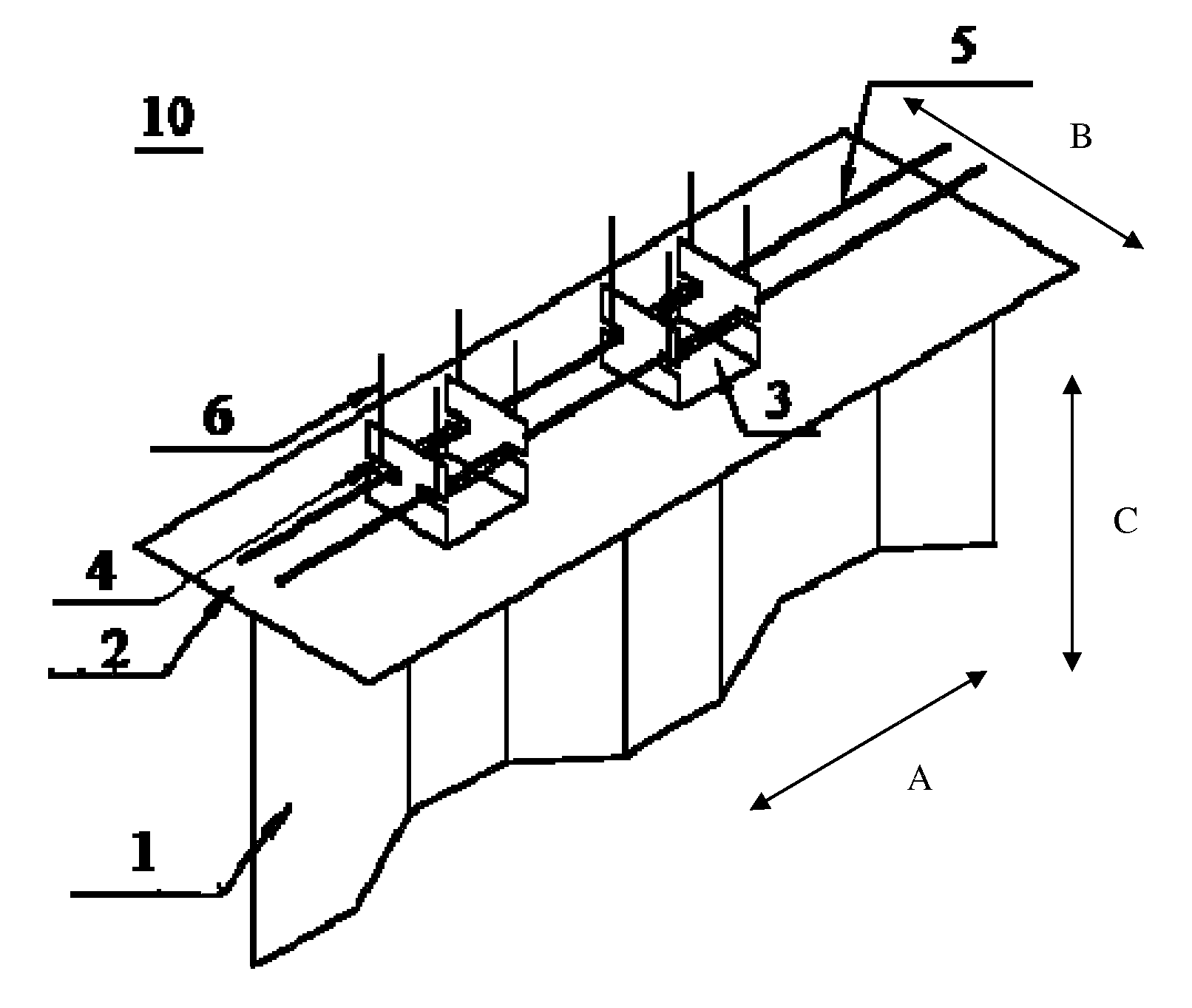
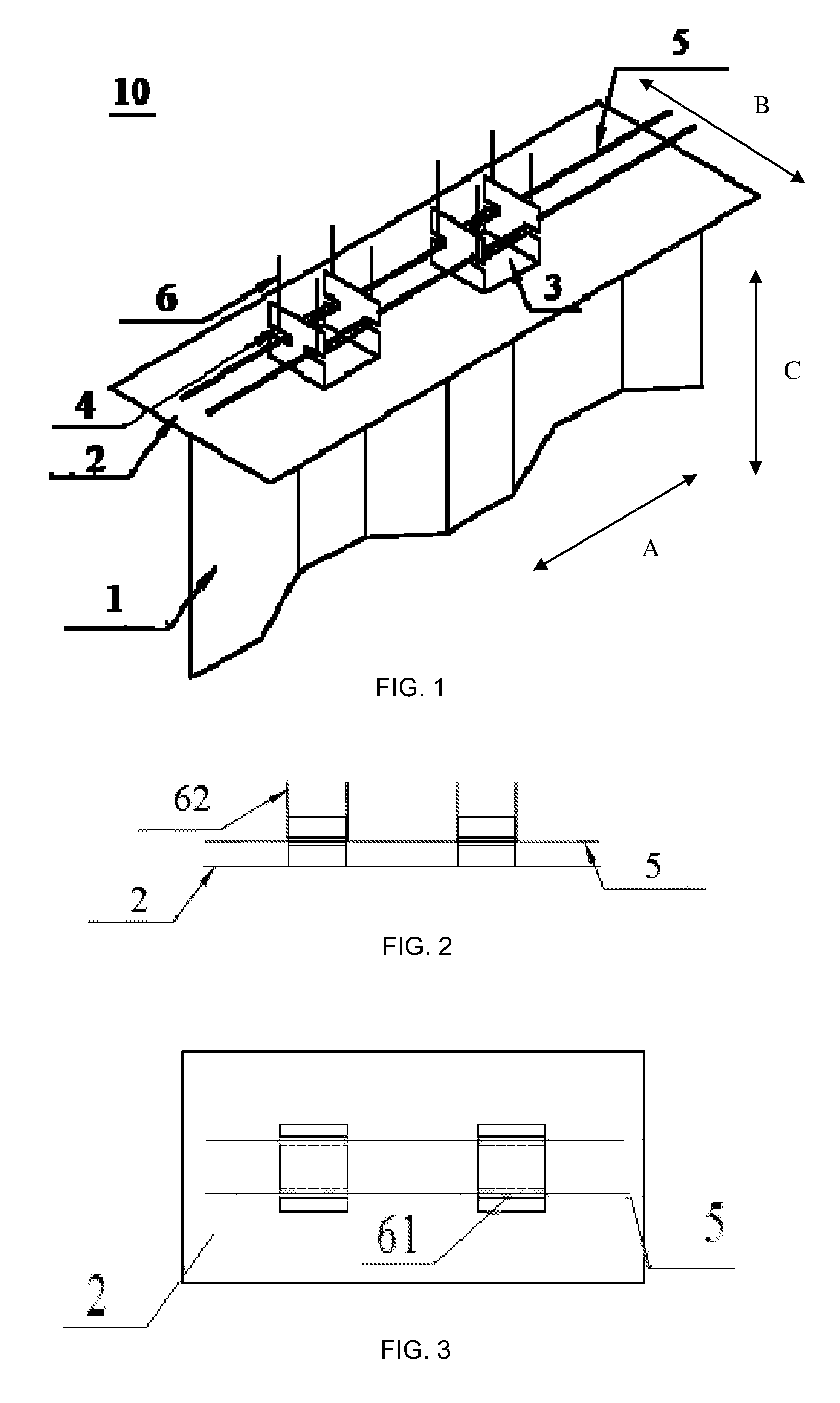
[0016]As shown in FIG. 1, a shear connector for corrugated sheet steel and concrete 10, comprises a corrugated sheet steel 1 and flange plate 2 welded at the upper end of the corrugated sheet steel, in the longitudinal direction A at an upper end of flange plate 2 (in the extending direction of the corrugated sheet steel) two U-shaped steel channels 3 are welded, the channel wall of each of the U-shaped steel channel 3 is located on the longitudinal side (in the extending direction of the corrugated sheet steel), on the left and right sides of the front and rear channel walls respectively, corresponding open grooves 4 extending in the lateral direction B are provided, within the grooves 4 on both left and right sides are respectively provided with longitudinal penetrating steel bars 5, which penetrate and connect two steel channels 3.

[0017]As shown in FIGS. 2 and 3, in th...


PUM


Abstract

A shear connector for corrugated sheet steel and concrete, comprises a flange plate welded at an upper end portion of the corrugated sheet steel, with more than one U-shaped steel channel welded in the longitudinal direction at an upper edge of the flange plate, the channel walls of each U-shaped steel channel being provided with two longitudinal sides, the left and right sides of the front and rear channel walls being respectively provided with corresponding holes or grooves, the left and right sides of the front and rear channel walls being respectively provided with corresponding holes or grooves, which penetrates and connects each of the steel channels; in the holes or grooves on the left and right sides of each U-shaped steel channel respectively, a vertically bent steel bar is provided, a bottom steel bar of each of the vertically bent steel bars penetrating the holes or grooves on the left or the right side in a longitudinal direction, both ends of the bottom steel bar being respectively bent upwards and extending to form a vertical steel bar.

Description

FIELD OF TECHNOLOGY[0001]This invention is in the field of bridges, as combined structures in civil engineering. It is designed for the shear connection structure of corrugated sheet steel or steel girders with concrete slabs.BACKGROUND[0002]The connection of the corrugated sheet steel with the concrete top slab and bottom slab has a direct bearing on the bearing capacity and safety performance of a bridge in composite structure, which is a highly critical technical link in the design of this type of bridges.[0003]The design of the connection must take into account whether the horizontal shear force occurring between the steel and concrete materials can be effectively transferred, to make sure that these two different materials jointly support the load.[0004]There are diversified types of connectors, roughly including steel bar connector, profile steel connector, cotter connector, and perforated steel plate connector, and according to different shear rigidity, connectors can be clas...

Claims


Application Information

Patent Timeline
Patent Type & Authority Patents(United States)
IPC IPC(8): E04C3/293E01D2/02E01D19/12E01D101/26
CPCE01D19/125E04C3/293E01D2/02E01D2101/268Y10T403/471E04C3/294E04C5/0645
Inventor ZHANG, JIANDONGLIANG, XINZHENGWANG, XINLIU, DUOHU, HUAIYUJI, JINGKUN
Owner JIANGSU TRANSPORTATION RES INST CO LTD
Why Eureka
Try Eureka