Cross steel plate water-stopping joint continuous concrete wall and joint construction method thereof

An underground diaphragm wall and steel plate water-stopping technology, applied in sheet pile walls, water conservancy projects, underwater structures, etc., can solve the problems of difficult protection, difficult pulling, short seepage curve, etc., and increase the anti-leakage performance. , Guarantee impermeability, improve the effect of shear strength

Inactive Publication Date: 2009-12-23
SHANGHAI TUNNEL ENGINEERING CO. LTD.
View PDF0 Cites 34 Cited by
  • Summary
  • Abstract
  • Description
  • Claims
  • Application Information

AI Technical Summary

Problems solved by technology

refer to Figure 5 , Image 6 It is a structural schematic diagram of two existing cross steel plates 10', 10" water-stop joints and reaction boxes 30', 30", but the longitudinal water-stop steel plates 11', 11" are short (generally 25cm), and the seepage curve is short , so that the leakage resistance and shear strength of the cross steel water-stop joint are not enough; and the unreasonable structure of the reaction box 30', 30" makes the cross steel plate 10', 10" prone to mud inclusion, which affects the leakage resistance of the joint performance, and it is difficult to clean the two warehouses; in addition, it is difficult to protect the 10′ and 10″ cross steel plate, and it is difficult to pull out the reaction box 30′ and 30″, and it is difficult to guarantee the wall cleaning effect

Method used


Image

  • Cross steel plate water-stopping joint continuous concrete wall and joint construction method thereof
  • Cross steel plate water-stopping joint continuous concrete wall and joint construction method thereof
  • Cross steel plate water-stopping joint continuous concrete wall and joint construction method thereof

Examples


Embodiment Construction

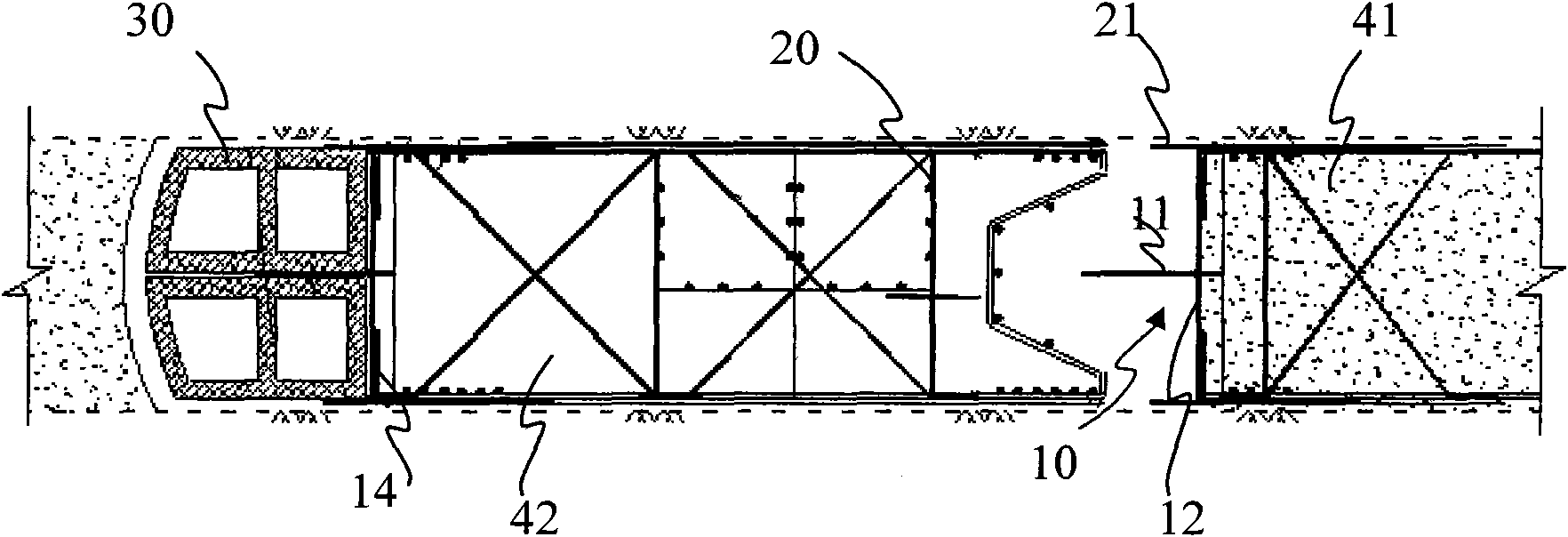
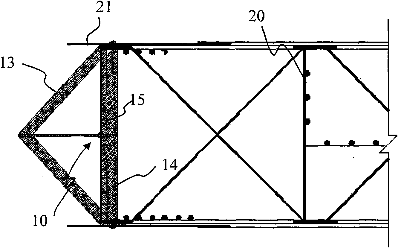
[0032] The cross-steel plate water-stop joint of the underground diaphragm wall and the construction method provided by the invention have good effects on the water-stop performance and shear strength of the ultra-deep underground diaphragm wall joint. The present invention will be further described below in conjunction with specific embodiments and accompanying drawings.

[0033] The waterproof performance of the joints of the ultra-deep underground diaphragm wall is very important to the safety of the foundation pit excavation. Since the foundation pit of the embodiment project enters the silt layer from 30m, a depressurization well is set in the pit before the excavation to carry out dewatering in the foundation pit. A large water head difference is formed inside and outside the pit. Once there is a danger of water leakage from the enclosure joints, it will be extremely difficult to plug the leak, which will have a fatal impact on the safety of the foundation pit and the sur...


PUM


Abstract

The invention provides a cross steel plate water-stopping joint of a continuous concrete wall and a joint construction method thereof. The cross steel plate joint comprises a longitudinal water-stopping steel plate and a horizontal head steel plate, wherein the longitudinal water-stopping steel plate is about 35-50 cm long, a detouring flow line of cement slurry is lengthened, the impermeability of the joint of the continuous concrete wall is enhanced, the bottom of the horizontal head steel plate extends to the tank bottom level or is inserted into the soil by 20 cm, and the detouring flow line of concrete and sand pulp along the bottom of the head steel plate is blocked; during constructing, a cross steel plate and a steel reinforcement cage are welded into a whole which is then deposited into a tank section so that the joint and a wall body have better integrity; a counterforce box is deposited at the back of the cross steel plate and is impacted to enter soil by over + / -30 cm, and then carpolite or clay are backfilled at the back for sealing; the concrete is cast in the tank section; the counterforce box is pulled out, then a flushing or shoveling tool corresponding to the cross steel plate in structure is adopted to remove the attachment at the part so as to ensure the water-stopping effect and the joint intensity of the cross steel plate.

Description

technical field [0001] The invention relates to a joint in an underground diaphragm wall and a construction method thereof during the construction of building enclosure engineering, in particular to a cross steel plate water-stop joint of an underground diaphragm wall and a construction method thereof. Background technique [0002] In the 1960s, the underground diaphragm wall construction technology was introduced into China. Due to its high rigidity, good anti-leakage performance, load-bearing capacity, and no vibration and noise during construction, it can be close to the edge of the building and is suitable for various Soil layer construction is therefore widely used in projects such as subway stations, cross-river passages, deep foundations of high-rise buildings, and anti-seepage dams, and has become a part of the enclosure structure or permanent structure of foundation pit excavation. Although the underground diaphragm wall is called a "diaphragm wall", it is actually ...

Claims


Application Information

Patent Timeline
Patent Type & Authority Applications(China)
IPC IPC(8): E02D5/18E02D29/16
Inventor 张瑞昌祝强马传锁戴兵姜民傅
Owner SHANGHAI TUNNEL ENGINEERING CO. LTD.
Why Eureka
Try Eureka