
Containment case and method of manufacture

a technology of containment cases and casings, applied in the field of containment cases, can solve the problems of fan blades becoming detached from the hub, affecting the case or casing of the fan, and affecting the engine of the aircraft, and achieves high interlaminar toughness at impact, high through-thickness shear strength, and high in-plane tensile strength

Active Publication Date: 2013-06-20
GENERAL ELECTRIC CO
View PDF6 Cites 35 Cited by
  • Summary
  • Abstract
  • Description
  • Claims
  • Application Information

AI Technical Summary

Benefits of technology

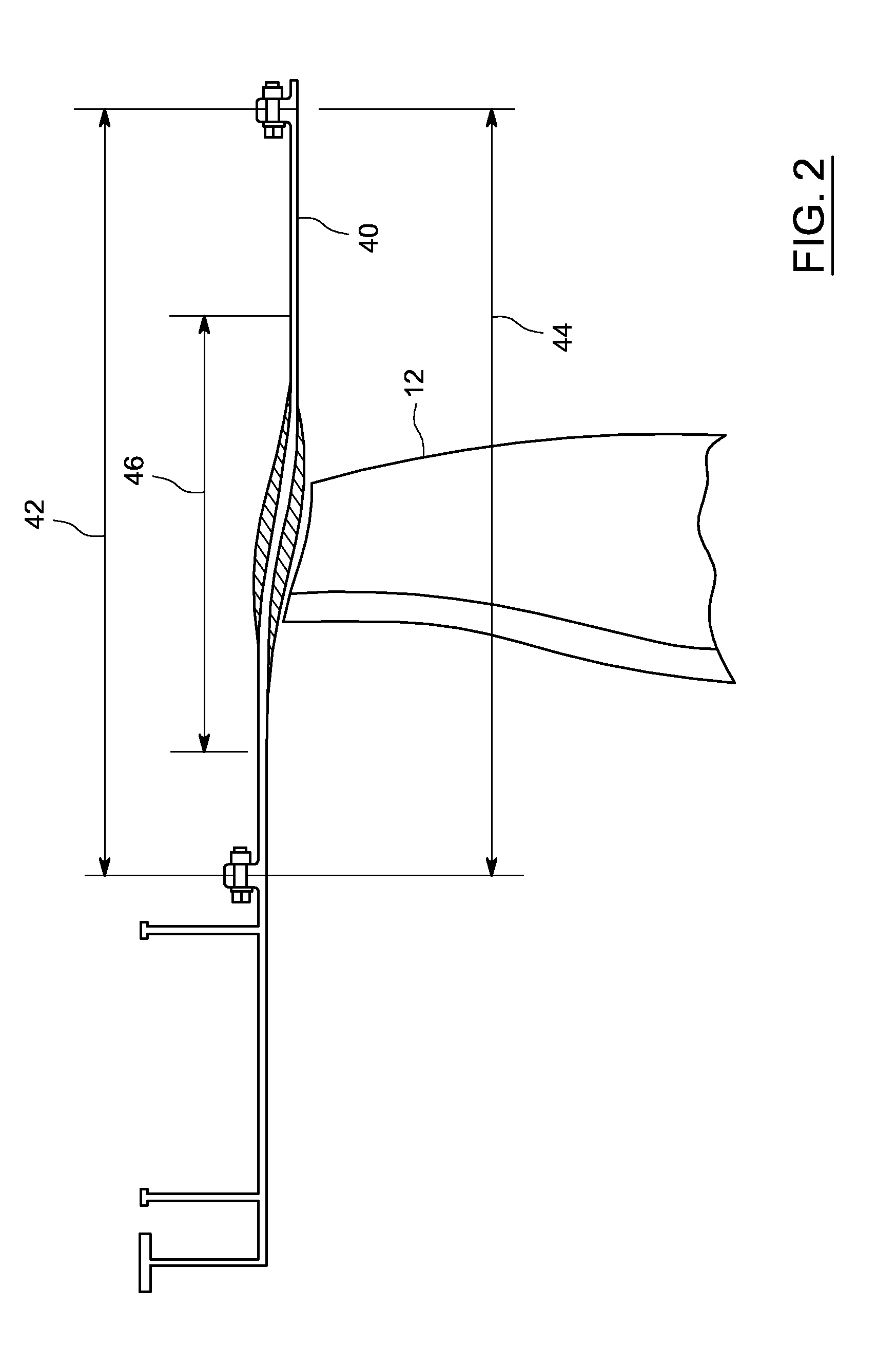
The patent describes a containment case for protective equipment that has two layers: a puncture-resistant layer and an energy capture layer. The puncture-resistant layer is made of a strong and tough material that is bonded to the inner surface of the containment case, while the energy capture layer is made of a strong but flexible material that is bonded to the outer surface of the containment case. These layers work together to provide impact resistance and protect the contents of the containment case.

Problems solved by technology

During the operation of such engines, there is a remote possibility that a foreign body, such as a bird, could impact the fan(s) and cause severe fan damage.
That damage could result in part or all of a fan blade becoming detached from the hub and impacting the fan case, or casing.
Such a detached fan blade could cause considerable damage to the aircraft powered by the engine if it were not contained by the fan case.
Similar damage could also result if the fan blade suffered failure through fatigue.
However, blade containment achieved by these methods generally incurs significant additional weight.
However, composites can be subject to puncture at the interior surface of the containment case.
In particular, composite blade containment cases are susceptible to damage due to sharp object impact.

Method used


Image

  • Containment case and method of manufacture
  • Containment case and method of manufacture
  • Containment case and method of manufacture

Examples


Embodiment Construction

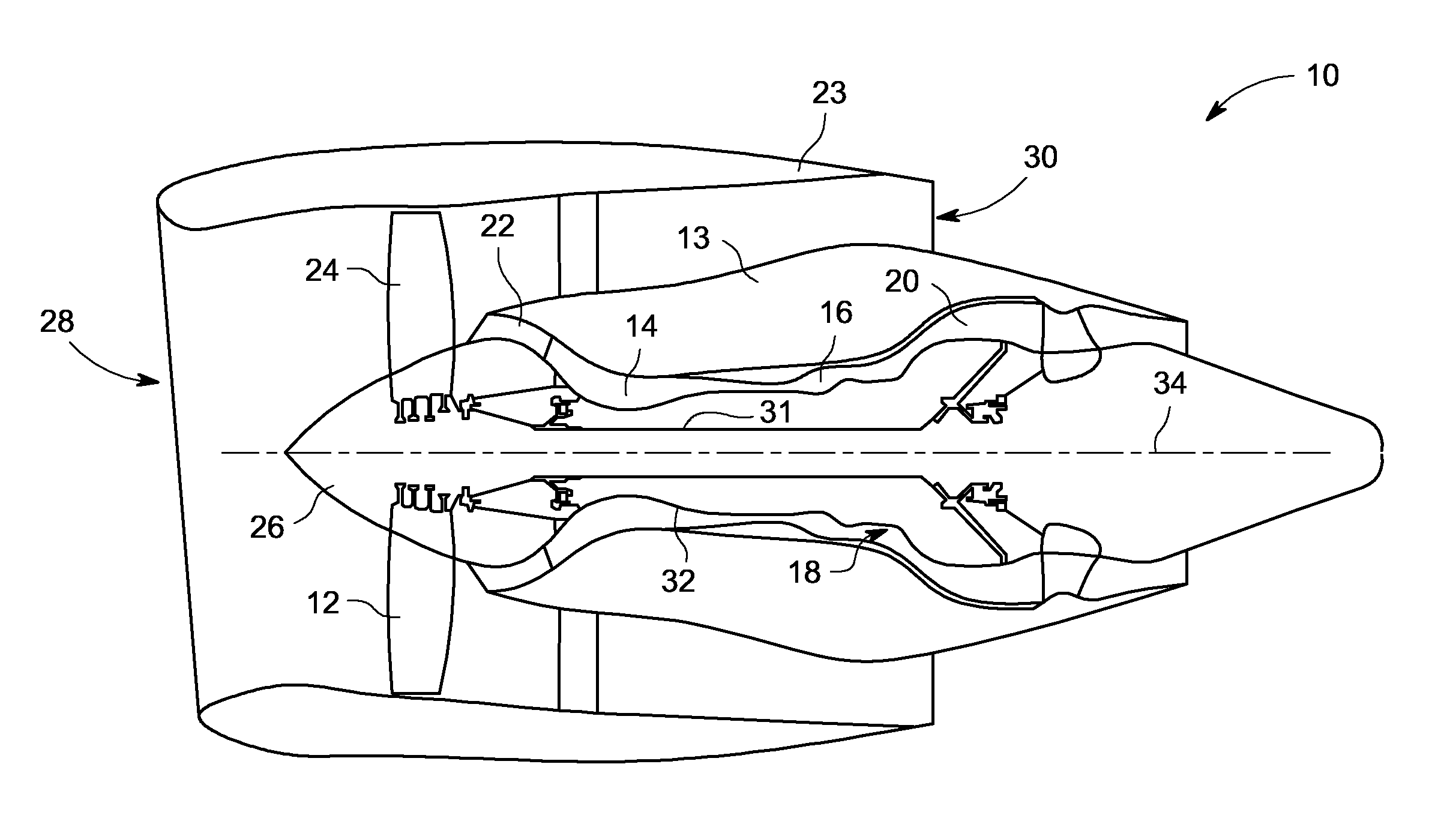
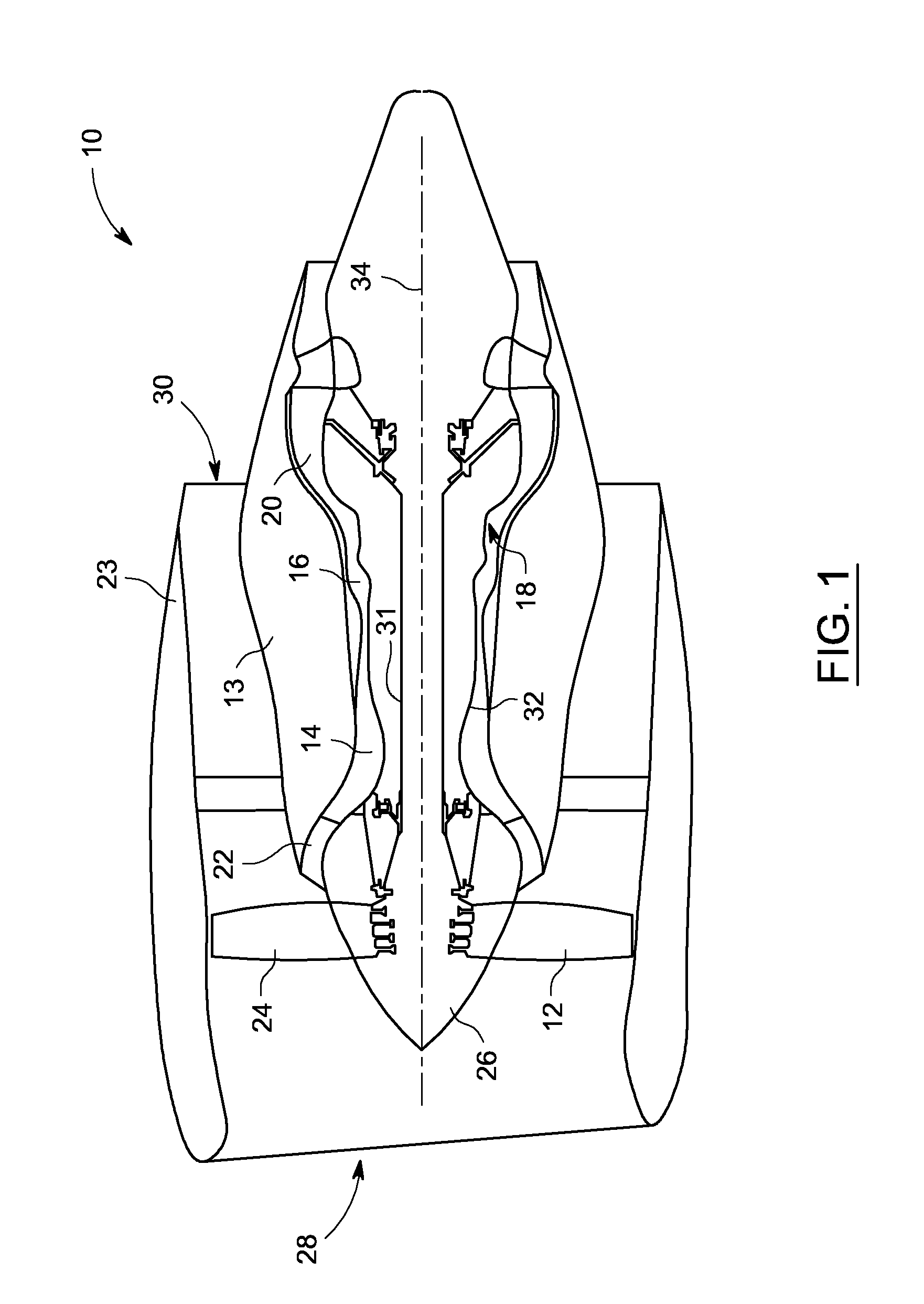
[0019]In the following description, like reference characters designate like or corresponding parts throughout the several views shown in the figures. It is also understood that terms such as “top,”“bottom,”“outward,”“inward,”“first,”“second,” and the like are words of convenience and are not to be construed as limiting terms. Furthermore, whenever a particular aspect of the invention is said to comprise or consist of at least one of a number of elements of a group and combinations thereof, it is understood that the aspect may comprise or consist of any of the elements of the group, either individually or in combination with any of the other elements of that group.

[0020]Referring to the drawings in general, it will be understood that the illustrations are for the purpose of describing particular embodiments of the blade containment case, system and method disclosed herein and are not intended to be limiting.

[0021]A blade containment case for a gas turbine engine is described in deta...


PUM

PropertyMeasurementUnit
porosityaaaaaaaaaa
porosityaaaaaaaaaa
porosityaaaaaaaaaa

Abstract

A containment case comprises a composite core, with an inner and outer surface, at least one puncture resistant layer bonded to the inner surface of the composite core and at least one energy capture layer bonded to the outer surface of the composite core. The puncture resistant layer having a high through-thickness shear strength and high interlaminar toughness at impact. The energy capture layer having a high in-plane tensile strength and low resistance to delamination and fiber-matrix debonding at impact. A method of fabricating a containment case includes the steps of disposing one or more layers of a puncture resistant material on a layup mandrel, disposing one more layers of a structural composite material on an exterior surface of the puncture resistant material, disposing one or more layers of an energy capture material on an exterior surface of the structural material and curing a resin in the plurality of layers.

Description

BACKGROUND[0001]The invention relates generally to containment cases and, more particularly, to containment cases with enhanced impact resistance.[0002]Gas turbine engines are extensively used to propel an aircraft. A typical turbofan engine includes large, ducted fans placed at the front of the engine. The fans serve to produce greater thrust and reduce specific fuel consumption. During the operation of such engines, there is a remote possibility that a foreign body, such as a bird, could impact the fan(s) and cause severe fan damage. That damage could result in part or all of a fan blade becoming detached from the hub and impacting the fan case, or casing. Such a detached fan blade could cause considerable damage to the aircraft powered by the engine if it were not contained by the fan case. Similar damage could also result if the fan blade suffered failure through fatigue. In order to prevent such damage, various containment systems have been employed. Conventional containment ca...

Claims


Application Information

Patent Timeline
Patent Type & Authority Applications(United States)
IPC IPC(8): B65D81/02B29C70/02
CPCB29K2995/0089B29L2031/7504B29C70/08Y02T50/672F01D5/282F01D25/24F01D5/28Y02T50/60
Inventor ZHU, QIFINN, SCOTT ROGER
Owner GENERAL ELECTRIC CO
Learn More