
Modular Planting System For Roof Applications

Inactive Publication Date: 2008-07-17
HORTECH
View PDF39 Cites 38 Cited by
  • Summary
  • Abstract
  • Description
  • Claims
  • Application Information

AI Technical Summary

Benefits of technology

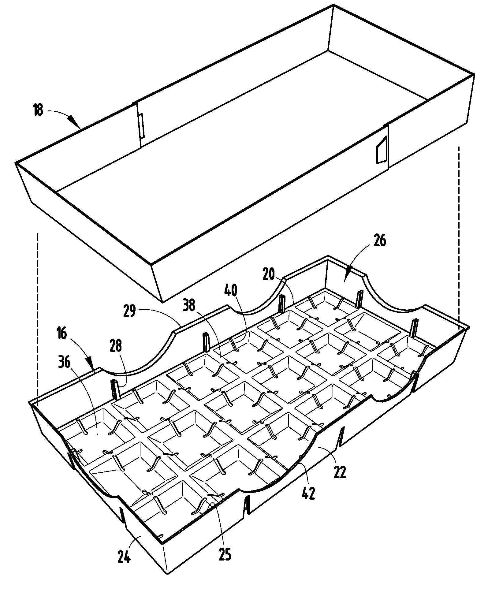
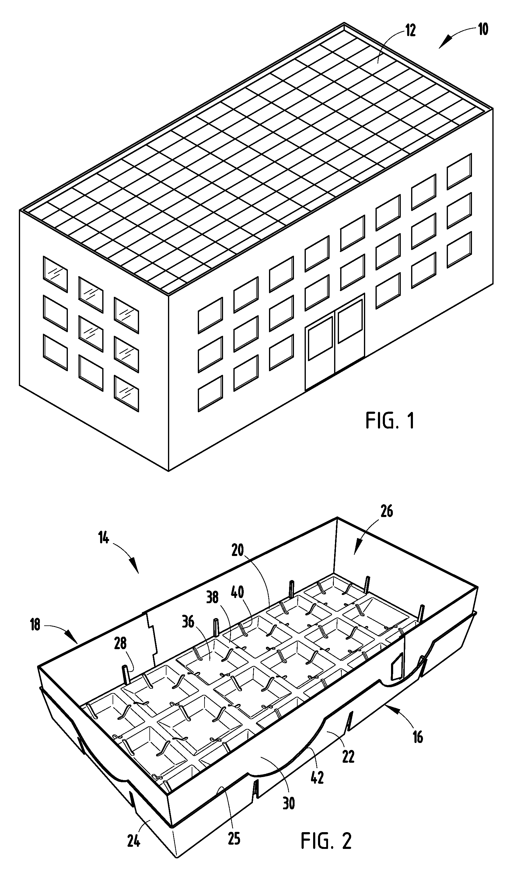
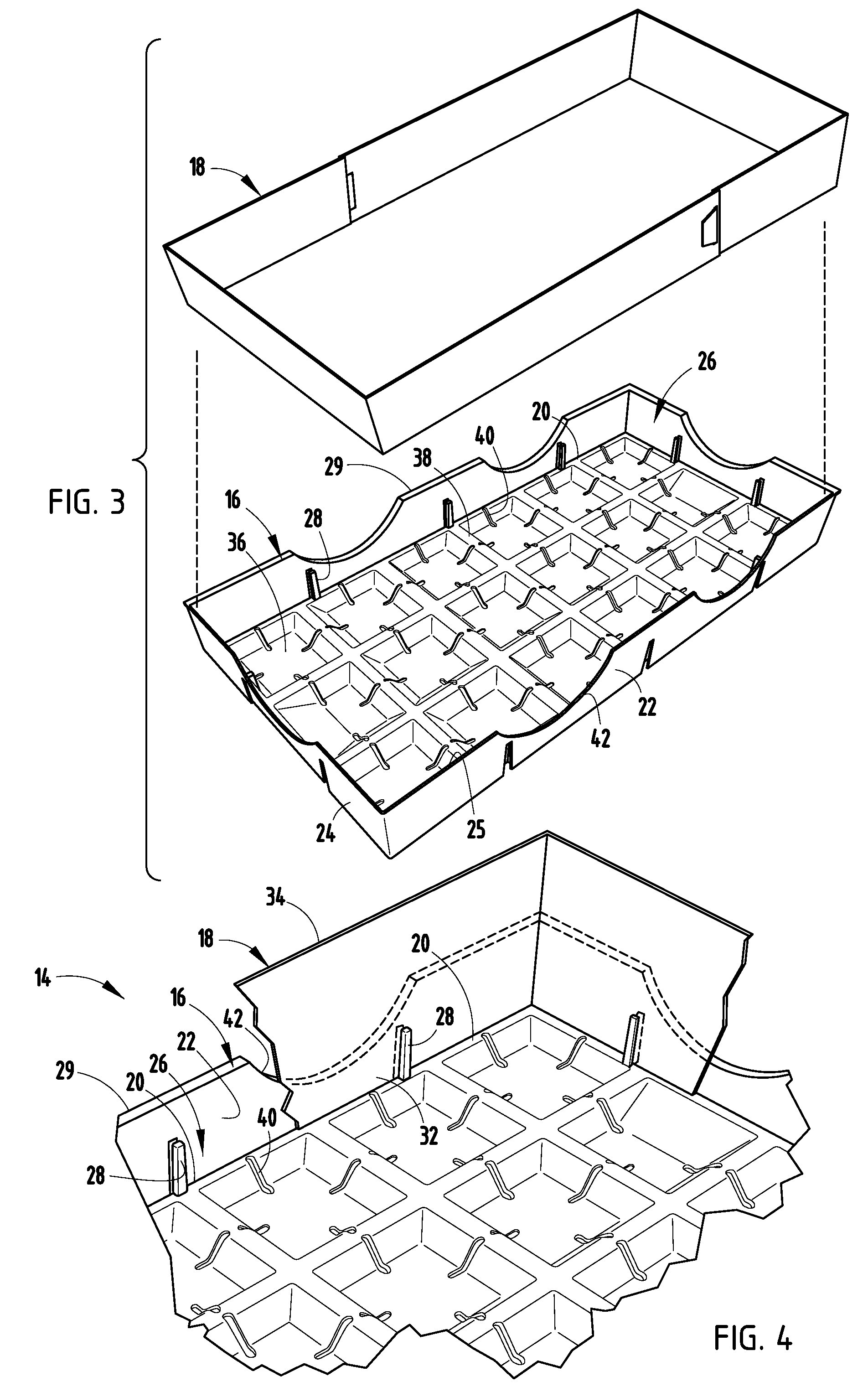
[0007]Yet another aspect of the present invention is to provide a green roof planter module that comprises a planter including a bottom wall, a plurality of sidewalls that cooperate with the bottom wall to form an interior space, and at least one aperture extending through at least one of the sidewalls of the plurality of sidewalls The planter module further comprises a removable collar member extending upwardly from at least a select one of the plurality of sidewalls, wherein the collar includes at least one relief therein, and wherein the collar member is adapted to retain a plant matter that extends above the plurality of sidewalls, and a retainer member that extends into the at least one aperture of the at least one sidewall of the planter and the at least one relief of the collar, thereby removably retaining at least a portion of the collar within the interior space of the planter.
[0009]Another aspect of the present invention is to provide a green roof planter module that comprises a planter including a bottom walt, and a plurality of sidewalls that cooperate with the bottom wall to form an interior space, wherein each of the sidewalls includes a top edge and a bottom edge, at Least one of the sidewalls of the plurality of sidewalls includes a relief extending through the at least one sidewall and extending greater than half of a distance between the top edge to the bottom edge of the at least one sidewall, wherein the relief is adapted to provide fluid communication between the planter module and a proximate second planter module.
[0010]Still yet another aspect of the present invention is to provide a green roof planter module that comprises a drainage member including a bottom surface, a top surface having at least one downwardly-extending recess, and a plurality of side surfaces, and a planter separate from the drainage member and including a bottom wall abutting the top surface of the drainage member and having at least one drainage aperture in fluid communication with the at least one recess of the drainage member, thereby allowing fluid communication between the at least one aperture and the at least one recess. The at least one recess extends through at least one of the plurality of side surfaces, thereby providing fluid communication between the planter module and an adjacent planter module.
[0011]The present inventive green roof system provides coverage of an entire roof area quickly and economically by allowing the associated modules to be grown off-sight in a manner that allows the plant matter to extend upwardly from an associated planter and plant matter within adjacent modules to abut immediately upon installation. Further, the roof system is easy to install at a relatively Low cost. Moreover, the system provides improved water communication and drainage between adjacent modules, allows easy maintenance of the overall system, can be installed easily and quickly by even unskilled personnel, is capable of a Long-operating life, and is particularly well adapted for the proposed use.

Problems solved by technology

However, this method typically requires a significant amount of time until the plants provide adequate coverage.
Such methods, while a vast improvement over previous methods, typically result in several months to years of grow time while the individual sections grow and subsequently fuse together to provide adequate roof coverage.
Another problem typically associated with past methods is the inadequacy of water supply, drainage and transport between the associated sections.

Method used


Image

  • Modular Planting System For Roof Applications
  • Modular Planting System For Roof Applications
  • Modular Planting System For Roof Applications

Examples


Embodiment Construction

[0023]For purposes of description herein, the terms “upper”, “lower,”“right,”“left,”“rear,”“front,”“vertical,”“horizontal,” and derivatives thereof shall relate to the invention as oriented in FIGS. 2 and 8. However, it is to be understood that the invention may assume various alternative orientations and step sequences, except where expressly specified to the contrary. It is also to be understood that the specific devices and processes illustrated in the attached drawings, and described in the following specification are exemplary embodiments of the inventive concepts defined in the appended claims. Hence, specific dimensions and other physical characteristics relating to the embodiments disclosed herein are not to be considered as limiting, unless the claims expressly state otherwise.

[0024]The reference numeral 10 (FIG. 1) generally designates a green roof system embodying the present invention and employed on a building roof 12 and comprising a plurality of individual green roof ...


PUM


Abstract

A modular planting system for roof applications includes a plurality of green roof planter modules each including a bottom wall, a plurality of sidewalls that cooperate with the bottom wall to form an interior space, and a plurality of support tabs extending inwardly towards the interior space. Each module further includes a removable collar member extending upwardly from the plurality of sidewalls, wherein the collar member is supported within the interior space by the support tabs, and wherein the collar member is adapted to retain a plant matter that extends above the sidewalls.

Description

BACKGROUND OF THE INVENTION[0001]The present invention relates to a modular planting system for roof applications, and in particular to a modular planting system that includes a plurality of planter modules each including a planter and a removable collar member extending upwardly from an uppermost portion of the planter, thereby allowing plant matter to extend above the upper edge of the associated planter and the removable collar to be removed once the planter module is placed adjacent to a plurality of other planter modules, thereby creating a green-roof system.[0002]Green-roof systems are used in a wide variety of applications, including commercial and residential buildings. The positive thermal properties of the systems result in significant cost savings with respect to cooling of the associated buildings and structures. Further, the systems dramatically reduce the amount of water runoff caused by rainfall, which is particularly critical in urban areas. The systems typically inc...

Claims


Application Information

Patent Timeline
IPC IPC(8): A01G9/02
CPCA01G9/02A01G9/022A01G9/033Y02B80/32Y02A30/254
Inventor MACKENZIE, DAVID S.
Owner HORTECH
Learn More