Roller fatigue test apparatus

Inactive Publication Date: 2008-07-17
GENTEK TECH MARKETING
View PDF5 Cites 24 Cited by
  • Summary
  • Abstract
  • Description
  • Claims
  • Application Information

AI Technical Summary

Benefits of technology

[0004]The invention provides a fatigue test machine useful in performing accelerated rolling contact fatigue endurance tests on the bearing rollers used in rol

Problems solved by technology

Because the bearing roller under test is loaded evenly between the three idler roller assemblies, it experiences

Method used


Image

  • Roller fatigue test apparatus
  • Roller fatigue test apparatus
  • Roller fatigue test apparatus

Examples


Embodiment Construction

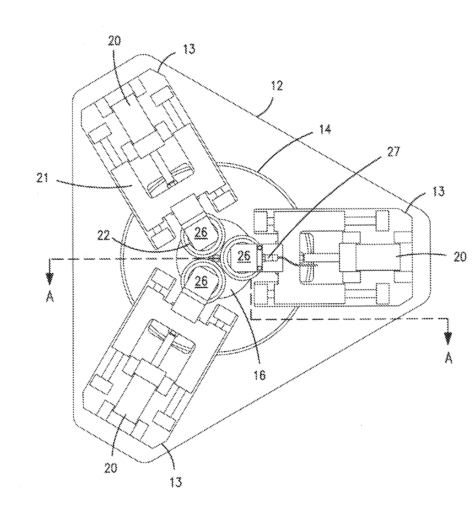
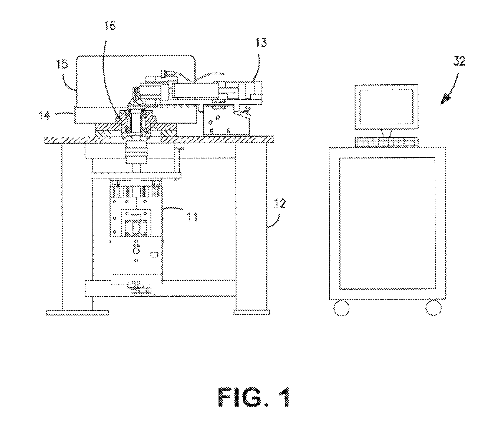
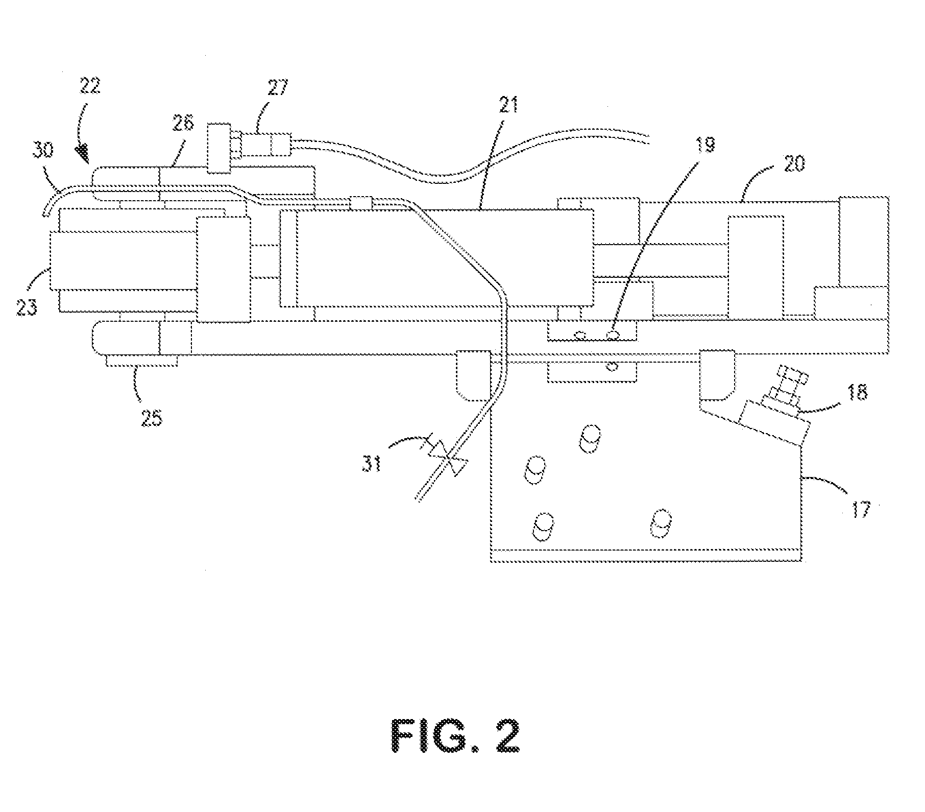
[0019]In the first embodiment of the testing machine of the invention as shown in FIG. 1, the test machine is comprised of a vertically oriented electric motor 11 that is suspended below a table-like frame 12. Mounted on top of the frame 12 are three load assemblies 13, an oil catch tray 14, a safety cover 15 and a spindle assembly 16. As shown in FIGS. 2 and 3, the load assembly 13 is comprised of a base 17 with tilt adjustment 18 and skew adjustment 19, on top of which is mounted a hydraulic cylinder assembly 20 and a cylinder carrier 21, the details of which are shown more clearly in FIG. 3 and which is guided by linear bearings (not shown?). Mounted to the carrier 21 alternatively may be either an idler roll assembly 22 or a tapped-mounting fixture (not shown) for securing tappet assemblies or similar assemblies. The idler roller assembly 22 is comprised of an idler roller ring 23 with a prescribed surface profile and finish, one or two rolling element bearings 24, a shaft 25 an...


PUM


Abstract

A machine suitable for evaluating finished cylindrical manufactured part that accurately simulates the performance of the intended use of the part in a cam-roller contact geometry using an actual manufactured part as the test specimen is provided. The machine is capable of evaluating the effects on the can finish and profile of the manufactured part. Three idler rollers ground to simulate the axial cam geometry are compressed into the outer diameter of the bearing as it rotates, duplicating the rolling action of a cam lobe. Because the cylindrical manufactured part to be tested is loaded evenly between the three idles, the test part experiences three stress cycles per revolution, accelerating the generation of fatigue spalling damage on the outside diameter. Load and speed are regulated using a closed loop control. Ease of replacing the part to be tested and servicing the idler rollers is an advantageous feature of the machine. A calibration fixture is provided for verifying that the machine is applying the specified load evenly on all three sides of the cylindrical manufactured part that is under test. Alternately the machine can be configured so as to enable the testing of three manufactured test specimens simultaneously. With the addition of a torque transducer, the torque generated between a journal bearing roller and shaft may be measured and monitored.

Description

[0001]The invention relates to a device for testing a range of finished cylindrical roller elements in rolling contact fatigue and has the flexibility of being reconfigured to also test a range of tappets. More particularly, the invention relates to a device having the aforementioned capability afforded by the utilization of three equally-spaced load cylinders configured alternatively (a) with means comprising cylindrical shaped idler rollers to apply a line contract load to three locations on a rotating cylindrical element undergoing testing: (b) with means of holding tappets or similar assemblies and loading them into a single driving idler roller; or (c) with means of holding a roller and axle assembly and loading them against a single driving roller and measuring the torque exerted on the axle.BACKGROUND OF THE INVENTION [0002]Known prior art test devices of this kind, for example, those disclosed in the Patent to Minter, U.S. Pat. No. 4,452,065 and the patent to Bacigalupo, et ...

Claims


Application Information

Patent Timeline
IPC IPC(8): G01N3/56
CPCG01N3/56G01N2203/0266G01N2203/0073
Inventor MAASSEN, ERIK C.BABCOCK, BRYCE W.
Owner GENTEK TECH MARKETING
Why Eureka
Try Eureka