Engine Fastener Of A Mounting System Interposed Between An Attachment Strut And An Aircraft Engine

a technology of mounting system and engine, which is applied in the direction of machines/engines, machine supports, other domestic objects, etc., can solve the problems of reducing the overall weight and size of the main body, affecting the overall size and weight of such a front attachment, and difficulty in transferring the effort in the attachment, so as to reduce the overall weight and size, reduce the length of the thrust p 6 absorption rod, and increase the overall weight

Active Publication Date: 2008-07-17
AIRBUS OPERATIONS (SAS)
View PDF3 Cites 43 Cited by
  • Summary
  • Abstract
  • Description
  • Claims
  • Application Information

AI Technical Summary

Benefits of technology

[0018]Consequently, the invention proposed permits an engine attachment to be obtained whose main body no longer requires the presence of a bearing in the rear part as was the case in the embodiments of the prior art, given that the hinge pin of the rudder bar is directly incorporated onto this main body. Consequently, it is the entire thinned rear part of the section of the main body that can be eliminated, which naturally leads to an advantageous reduction in the overall weight and size of this body.
[0019]Furthermore, eliminating the rear part with the thinned section allows the position of the hinge pin to be moved forward with respect to the position previously used. Consequently, the length of the thrust P 6 absorption rods may also be reduced, which advantageously leads to a gain in terms of the overall weight and size of the engine attachment.
[0020]Furthermore, the design of the main body proposed by the invention resolves the safety problem observed with the bolt used in the embodiments of the prior art in order to ensure the geometry of the bearing of the hinge pin. In fact, using two portions of pin that jointly compose the first hinge pin permits this safety to be achieved, which is also called a “Fail Safe” function.
[0021]It is also pointed out that the absence of a major difference in thickness in the attachment body allows the transfer of the efforts in the engine attachment to be significantly improved.

Problems solved by technology

This engine attachment is known in the prior art and firstly has a disadvantage in that the rear parts of the main braces have to be attached to one another downstream of the bearing formed by them, in order to ensure the geometry of this bearing.
This attachment, for example created using a bolt, is on the one hand a constraint in that it is in addition to the attachments already required to ensure that the two main braces are held mechanically, and on the other hand detrimental in that it doesn't incorporate a double safety system that is needed to provide the safety level mentioned above.
Moreover, the need to provide this rear part exclusively to hold the hinge pin of course implies that the overall weight and size of the main body are not fully optimised.
Furthermore, the position of the bearing housing the hinge pin is very much pushed back and requires the presence of two very long rods, which are also detrimental in terms of the overall size and weight of such a front attachment.
Finally, it should be noted that the difference in thickness between the central part and the rear part of the attachment body causes difficulties in transferring the efforts in the attachment.

Method used


Image

  • Engine Fastener Of A Mounting System Interposed Between An Attachment Strut And An Aircraft Engine
  • Engine Fastener Of A Mounting System Interposed Between An Attachment Strut And An Aircraft Engine
  • Engine Fastener Of A Mounting System Interposed Between An Attachment Strut And An Aircraft Engine

Examples


Embodiment Construction

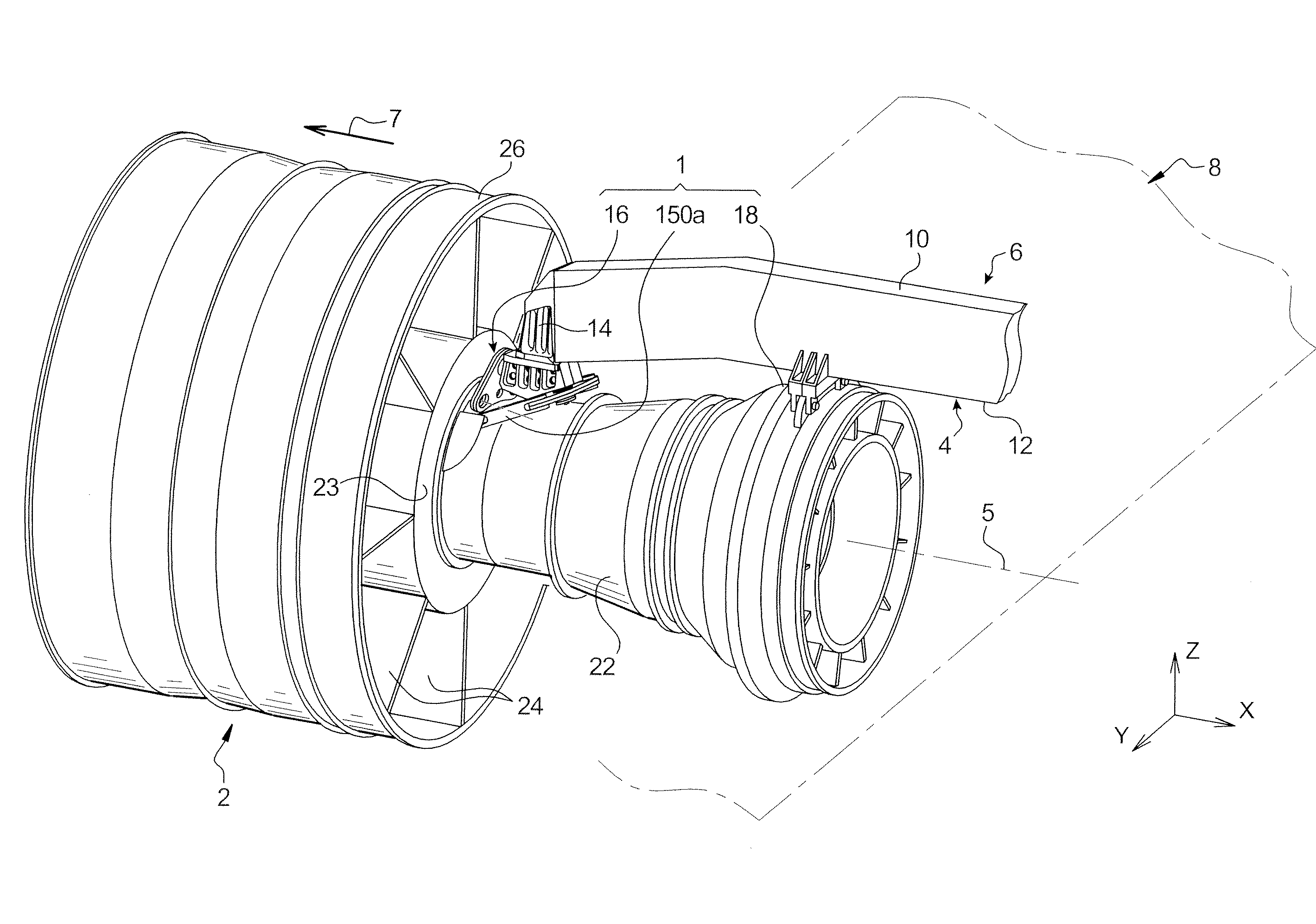
[0040]In reference first of all to FIG. 3, an assembly system 1 in one preferred embodiment of this invention is shown, wherein this assembly system 1 is mounted between an aircraft engine 2 and a rigid structure 4 of an attachment strut 6 fixed underneath the wing of an aircraft that is only shown diagrammatically for obvious reasons of simplicity, and generally designated by the numerical reference 8. It should be noted that the assembly system 1 is adapted to cooperate with a turbojet engine 2, but of course it could also operate with a system designed to hold any other type of engine, such as a turboprop engine, within the scope of the invention. Furthermore, the application of the assembly system 1 is not restricted to the example shown in FIG. 3 where the engine 2 is designed to be suspended underneath the wing 8 of the aircraft.

[0041]In the entire description below, by convention, the longitudinal direction parallel to the longitudinal axis 5 of the engine 2 will be called X,...


PUM


Abstract

An engine attachment for an assembly system configured to be mounted between a rigid structure of an attachment strut of an aircraft engine and an engine. The attachment includes a main body, a rudder bar on an articulated mounting on the main body by a hinge pin, and two thrust absorption rods each with one end connected to the rudder bar. The main body includes a first main brace and a second main brace superimposed on the first brace. The hinge pin is formed by a first portion and a second portion, wherein the first portion is made in one piece with the first brace and the second portion is made in one piece with the second brace. Furthermore, the braces define a stop limit surface configured to limit rotation of the rudder bar.

Description

TECHNICAL FIELD[0001]This invention relates generally to an engine attachment of an assembly system designed to be mounted between a rigid structure of an attachment strut of an aircraft engine and an engine, and more particularly but not exclusively to a front attachment designed to absorb the efforts which are exerted in the longitudinal, transversal and vertical directions of the engine.[0002]The invention also relates to an assembly system designed to be mounted between a rigid structure of an attachment strut of an aircraft engine and an engine, wherein this system can be used regardless of the position of the engine with respect to that of the attachment strut.STATE OF THE PRIOR TECHNIQUE[0003]An attachment strut of an aircraft is provided to form the connection interface between an engine and a wing of the aircraft. It allows the efforts generated by its engine to be transmitted to the structure of this aircraft, and also allows the passage of fuel, electricity, hydraulics an...

Claims


Application Information

Patent Timeline
Patent Type & Authority Applications(United States)
IPC IPC(8): B64D27/12B64D27/18
CPCY02T50/44B64D27/26B64D2027/268Y02T50/40
Inventor BEAUFORT, JACQUESDUMONT, JEAN-FRANCOIS
Owner AIRBUS OPERATIONS (SAS)
Why Eureka
Try Eureka