Conductor for an electrochemical energy store

a technology of electrochemical energy and conductor, which is applied in the direction of cell components, sustainable manufacturing/processing, and final product manufacturing, etc., can solve the problems of reducing reducing the weight of the conductor and material cost, and unnecessary new equipment purchase, so as to improve the ecobalance of the product, reduce the weight of the conductor and material cost, and facilitate the manufacture of the conductor

Inactive Publication Date: 2014-09-18
ROBERT BOSCH GMBH
View PDF14 Cites 7 Cited by
  • Summary
  • Abstract
  • Description
  • Claims
  • Application Information

AI Technical Summary

Benefits of technology

[0019]The present invention also relates to an example method for manufacturing a conductor for an electrochemical energy store, whereby the conductor may have a base body and at least one electrically conductive layer situated at least partially on the base body, and including at least the following steps: providing the base body, whereby the base body may include a non-electrically conductive material, and applying at least one electrically conductive layer at least partially to the base body. Using this method it is possible to easily manufacture a conductor according to the present invention. With the aid of this example method, it is possible to omit the use of a solid metal body when manufacturing the conductor, as a result of which the weight of the conductor and material costs and manufacturing costs of the conductor may be reduced. In addition, thinner conductors may be manufactured by using the method which otherwise could not be manufactured using a solid metal body given the presently known manufacturing techniques. Furthermore, use of the conductor manufactured using the method may also improve the ecobalance of the product in which the conductor is used, since a lighter weight may reduce transport costs and the energy consumption of the product.
[0020]It may be advantageous if in the example method an active material is applied at least partially to at least one conductive layer. For example, the electrically conductive layer situated on the base body may include a metal, copper, for example, and applied to the copper may be an active material, for example, selected from a group composed of graphite, silicon and / or titanate Li4Ti5O12, so that, for example, the electrically conductive layer and the active material form an anode. Furthermore, a second conductive layer, for example, a metal, in particular aluminum, may be situated on a second side of the base body, the second side being situated opposite the first side, and a second active material, selected for example from a group consisting of lithium metal oxide LiMeO such as LiNixCoyMnzO2, LiNixCorAlzO2, LiCoO2, LiNiO2, LiMn2O4 or LiFePO4 may be situated on the second conductive layer so that, for example, the second electrically conductive layer and the second active material form a cathode. In this way the conductor may be advantageously designed as a combination electrode, making it advantageously possible to save on material costs and also on installation space in the energy store. In addition, production of the conductor in conjunction with the method according to the present invention may be further simplified, resulting in further reduced manufacturing costs.
[0021]It may be advantageous if in the method at least one electrically conductive layer is applied to the base body by coating, laminating or printing. The different forms of application make it possible to adapt the manufacturing process of the conductor to existing manufacturing techniques and equipment. This may make it unnecessary to purchase new equipment. In addition, an active material may be at least partially applied to the at least one electrically conductive layer in the same manner as the electrically conductive layer. Thus, in this method it may be possible for an anode, for example, in the form of the first electrically conductive layer and the first active material situated thereon to be formed on the first side of the base body of the conductor, and on the second side of the base body a cathode in the form of the second electrically conductive layer and the second active material situated thereon. For example, in this method the base body may be present as a metalized foil in the form of a coil, which is unrolled and, with the aid of a coating / drying facility, the surface of which is coated with an active material. The metalized foil may include a plastic foil which may be metalized with a metal, for example, by sputtering, of a chemical or electrochemical coating. In this way, the conductor may be designed as a combination electrode, whereby, for example, material, labor costs, storage costs, weight and manufacturing costs of the electrochemical energy store may be further reduced.

Problems solved by technology

The separator must be permeable to the ions, however, which cause the conversion of the stored chemical energy into electrical energy.
In addition, thinner conductors may be manufactured by using the method which otherwise could not be manufactured using a solid metal body given the presently known manufacturing techniques.
Furthermore, use of the conductor manufactured using the method may also improve the ecobalance of the product in which the conductor is used, since a lighter weight may reduce transport costs and the energy consumption of the product.
This may make it unnecessary to purchase new equipment.

Method used


Image

  • Conductor for an electrochemical energy store
  • Conductor for an electrochemical energy store
  • Conductor for an electrochemical energy store

Examples


Embodiment Construction

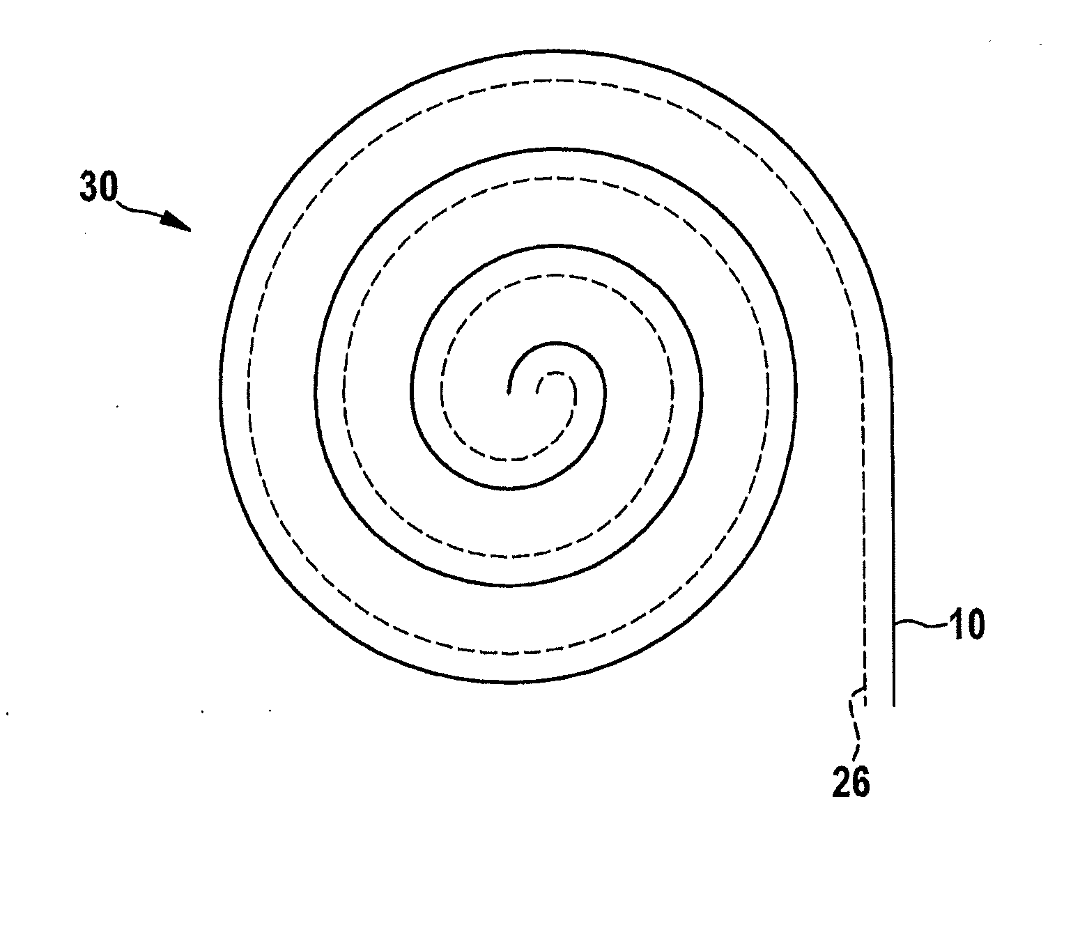
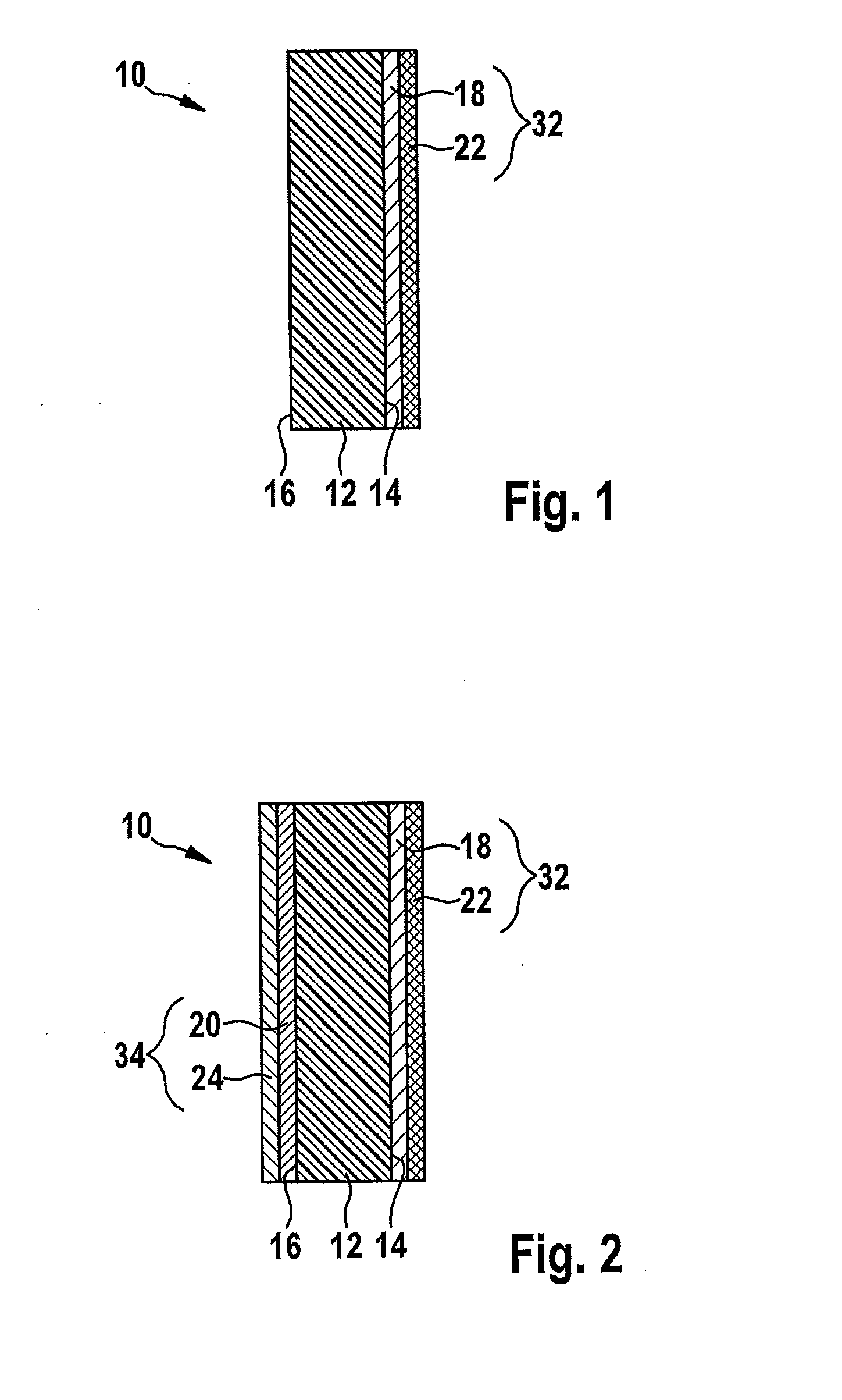
[0030]FIG. 1 shows a conductor 10 for an electrochemical energy store30. The conductor includes a base body 12 and at least one electrically conductive layer 18 situated at least partially on base body 12. In this exemplary embodiment base body 12 includes a polymer. The polymer in this example has a density of less than or equal to 2.7 g / cm3. Electrically conductive layer 18 situated at least partially on base body 12 includes a metal; in this exemplary embodiment it is copper.

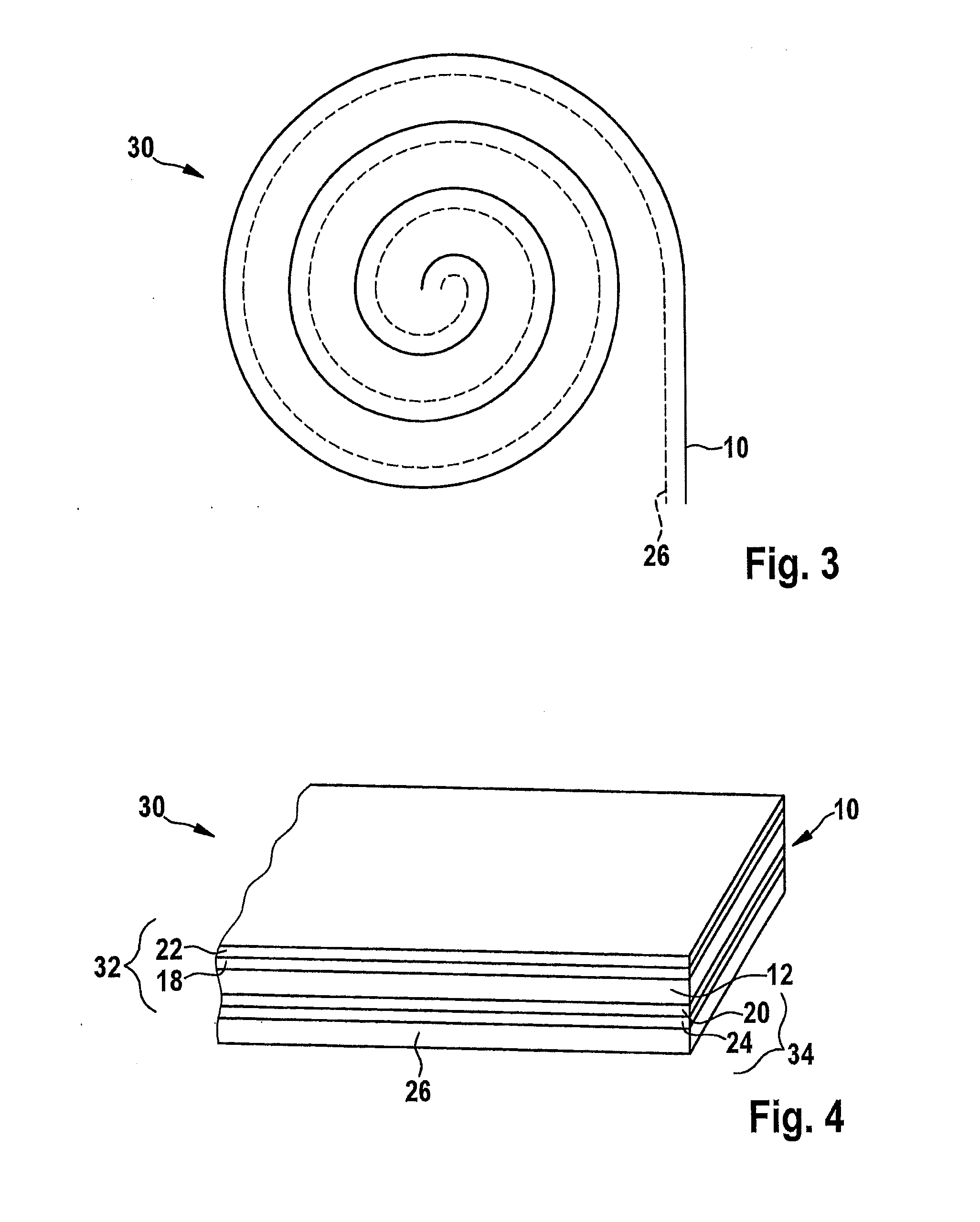
[0031]Although not shown in FIG. 1, base body 12 of conductor 10 has a foil-like design, base body 12 having a plane extension. The foil-like configuration of base body 12 and the resultant plane extension are shown in FIG. 4.

[0032]In FIG. 1, base body 10 includes a first side 14 on its plane extension and a second side 16 situated opposite first side 14.

[0033]As is apparent in FIG. 1, a first conductive layer 18 is situated on first side 14 of base body 12. First electrically conductive layer 18 includes at ...


PUM

PropertyMeasurementUnit
densityaaaaaaaaaa
densityaaaaaaaaaa
densityaaaaaaaaaa

Abstract

A conductor is describing for an electrochemical energy store, including a base body, and at least one electrically conductive layer situated at least partially on the base body. The base body includes a non-electrically conductive material. In addition, an energy store is described which is equipped with the conductor, a method for manufacturing a conductor is described, and the use of the energy store equipped with the conductor in an electrical device is described.

Description

CROSS REFERENCE[0001]The present application claims the benefit under 35 U.S.C. §119 of German Patent Application No. DE 10 2013 204 226.4 filed on Mar. 12, 2013, which is expressly incorporated herein by reference in its entirety.FIELD[0002]The present invention relates to a conductor for an electrochemical energy store, an energy store equipped therewith, a method for manufacturing the conductor and the use of the energy store equipped with the conductor in an electronic component.BACKGROUND INFORMATION[0003]In electrochemical energy stores, for example, lithium ion batteries, solid metal bodies in particular, such as metal foils made, for example, of copper or aluminum are used as both carrier and as conductor material.[0004]Moreover, in the manufacture of such energy stores, for example, in the form of a wound cell, both sides of these solid metal bodies are coated, for example, either with anode material or with cathode material. During manufacture of the energy store, correspo...

Claims


Application Information

Patent Timeline
Patent Type & Authority Applications(United States)
IPC IPC(8): H01M4/70H01M4/04H01B1/16H01M50/528
CPCH01M4/70H01M4/0402H01B1/16H01M4/661H01M4/667H01M4/668H01M10/0525H01B1/122Y10T29/49115Y02E60/10Y02P70/50
Inventor SCHUETZBACH, PETERGLOCK, ARMIN
Owner ROBERT BOSCH GMBH
Why Eureka
Try Eureka