Semiconductor structure with field shield and method of forming the structure.

a semiconductor and field shield technology, applied in the field of semiconductor structures with field shields and methods of forming structures, can solve the problems of affecting the yield and/or reliability of circuits, affecting the performance of circuits,

Active Publication Date: 2008-07-17
GLOBALFOUNDRIES U S INC
View PDF7 Cites 1 Cited by
  • Summary
  • Abstract
  • Description
  • Claims
  • Application Information

AI Technical Summary

Benefits of technology

[0008]The local interconnect can comprise a conductor. Specifically, this conductor can be located adjacent to a selected doped semiconductor region (i.e., adjacent to a source / drain region of a field effect transistor or adjacent to an anode or cathode of a diode) and can extend vertically through the second isolation layer to the conductive pad such that it electrically couples the conductive pad to the selected doped semiconductor region. This local interconnect (i.e., the conductor) will shunt current that passes into the device to the conductive pad so as to prevent the build up of an electric charge in the second isolation layer. The conductive pad will further protect the device from any electric charge that is built up in the first isolation layer and the substrate.
[0009]The conductive pad and the conductor can each comprise a suitable conductive material, for example, a doped polysilicon or a conductive metal. Additionally, the structure can comprise a metal strap that bridges both the conductor and the doped semiconductor region, thereby allowing current to flow easily between the device and local interconnect to the field shield even if the conductor and the adjacent doped semiconductor region of the device are doped with different type dopants.

Problems solved by technology

Silicon-on-insulator (SOI) technology and, particularly, partially depleted SOI technology, is often subject to damage during wafer processing in the back-end of the line (BEOL) sectors.
The presence of this current in the BOX can lead to a trapped electronic charge.
The trapped electronic charge in the BOX can alter the electrical properties of the semiconductor devices and, thereby, degrade yield and / or reliability of circuits.

Method used


Image

  • Semiconductor structure with field shield and method of forming the structure.
  • Semiconductor structure with field shield and method of forming the structure.
  • Semiconductor structure with field shield and method of forming the structure.

Examples


Embodiment Construction

[0029]The embodiments of the invention and the various features and advantageous details thereof are explained more fully with reference to the non-limiting embodiments that are illustrated in the accompanying drawings and detailed in the following description. It should be noted that the features illustrated in the drawings are not necessarily drawn to scale. Descriptions of well-known components and processing techniques are omitted so as to not unnecessarily obscure the embodiments of the invention. The examples used herein are intended merely to facilitate an understanding of ways in which the embodiments of the invention may be practiced and to further enable those of skill in the art to practice the embodiments of the invention. Accordingly, the examples should not be construed as limiting the scope of the embodiments of the invention.

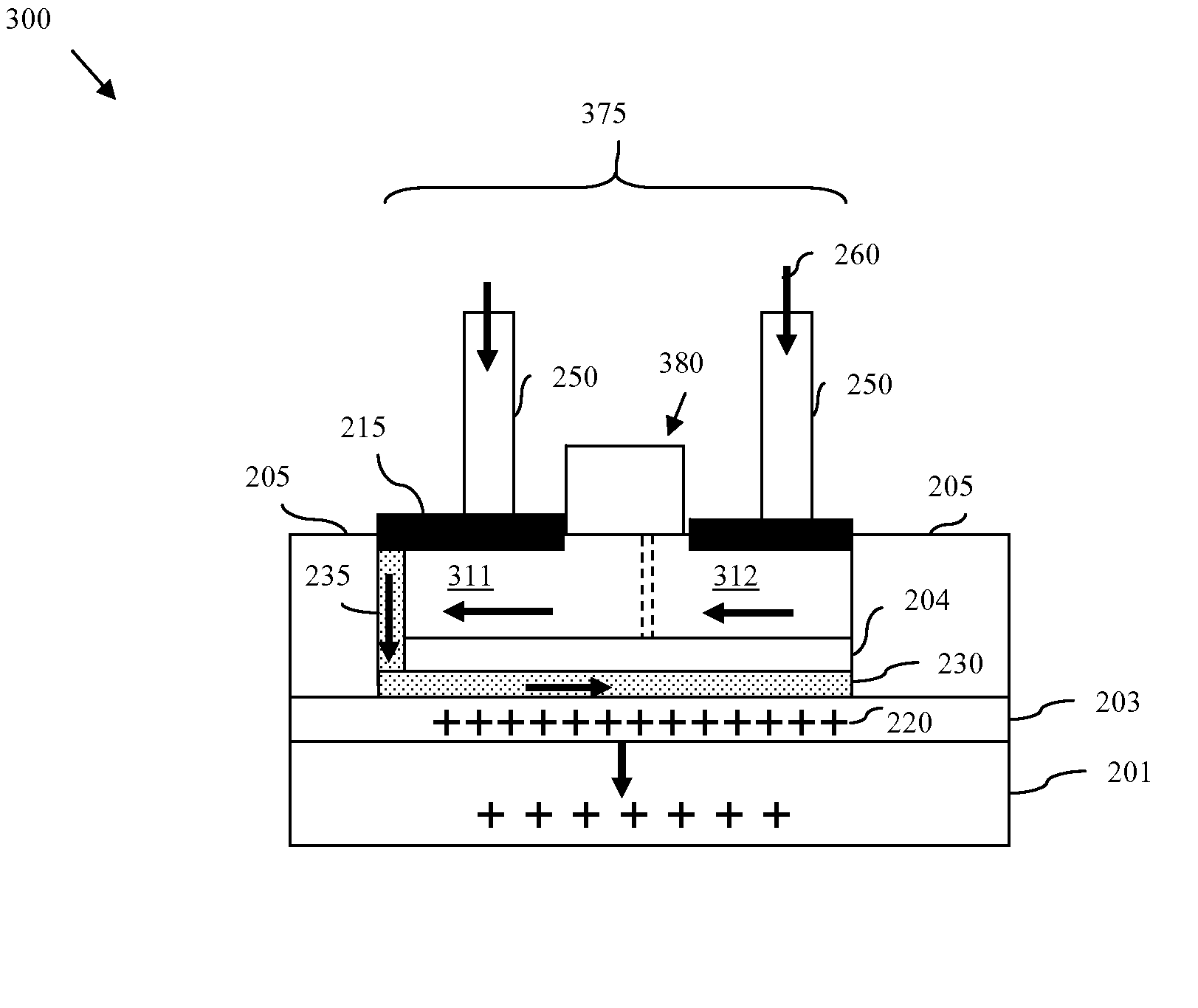
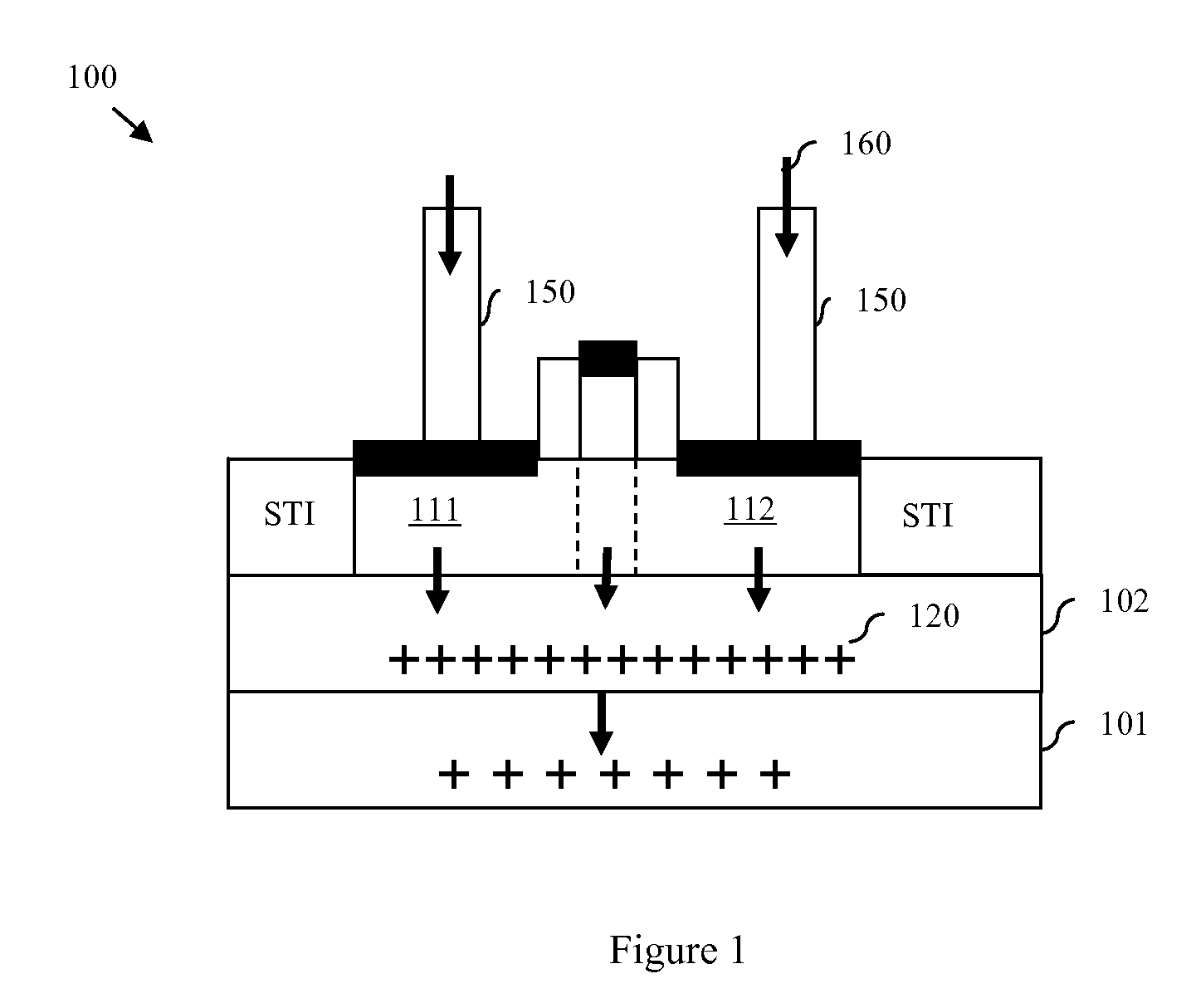
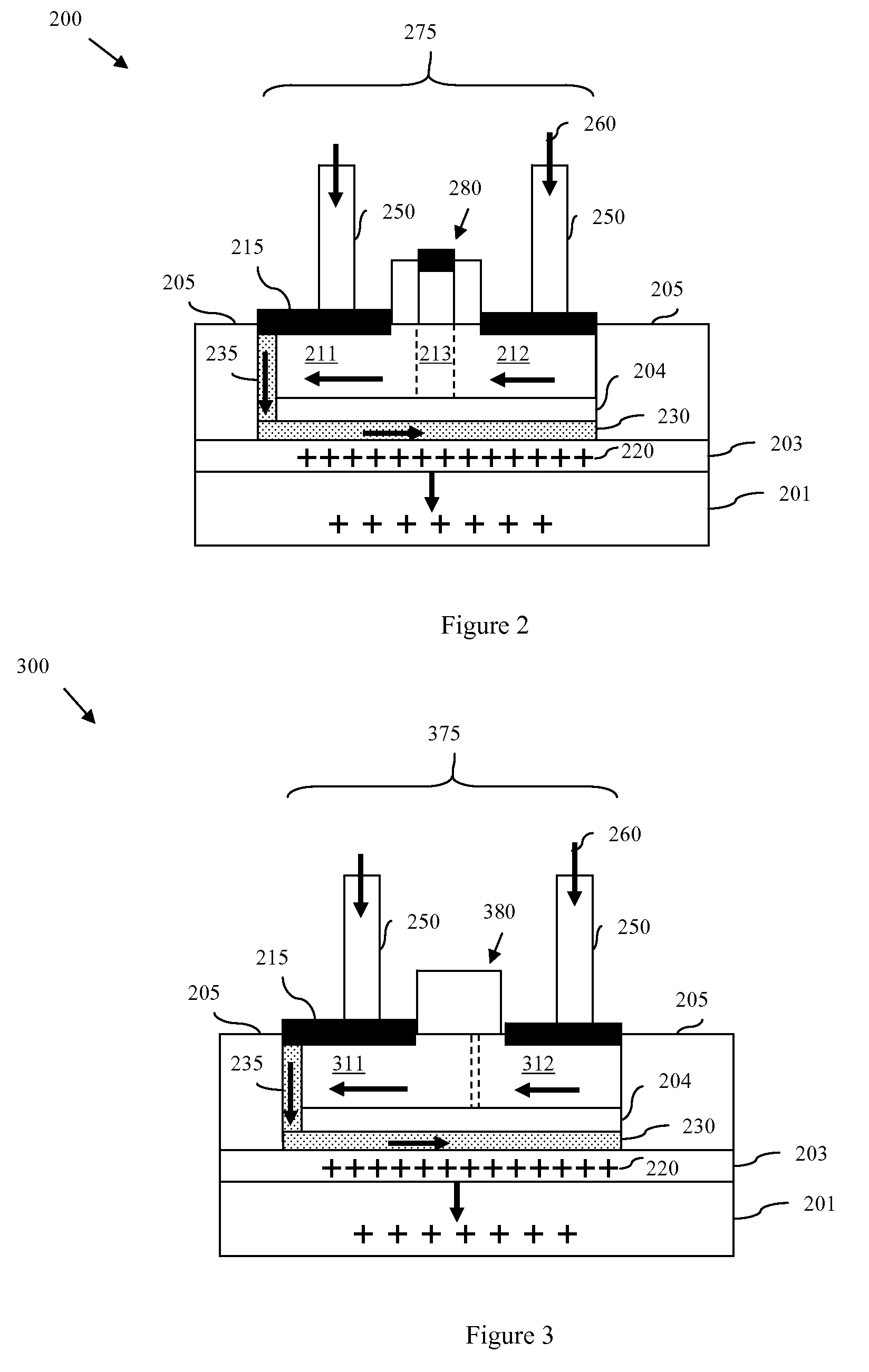
[0030]As mentioned, silicon-on-insulator (SOI) technology and, particularly, partially depleted SOI technology, is often subject to damage durin...


PUM


Abstract

Disclosed is semiconductor structure that incorporates a field shield below a semiconductor device (e.g., a field effect transistor (FET) or a diode). The field shield is sandwiched between upper and lower isolation layers on a wafer. A local interconnect extends through the upper isolation layer and connects the field shield to a selected doped semiconductor region of the device (e.g., a source / drain region of a FET or a cathode or anode of a diode). Current that passes into the device, for example, during back-end of the line charging, is shunted by the local interconnect away from the upper isolation layer and down into the field shield. Consequently, an electric charge is not allowed to build up in the upper isolation layer but rather bleeds from the field shield into the lower isolation layer and into the substrate below. This field shield further provides a protective barrier against any electric charge that becomes trapped within the lower isolation layer or substrate

Description

BACKGROUND[0001]1. Field of the Invention[0002]The embodiments of the invention generally relate to semiconductor devices and, more particularly, to a semiconductor structure that incorporates a semiconductor device coupled to a field shield.[0003]2. Description of the Related Art[0004]Silicon-on-insulator (SOI) technology and, particularly, partially depleted SOI technology, is often subject to damage during wafer processing in the back-end of the line (BEOL) sectors. Specifically, charging of metal lines in processing tools can pass a current from the on-wafer wires through semiconductor devices and into the buried oxide (BOX) before exiting the substrate wafer. The presence of this current in the BOX can lead to a trapped electronic charge. The trapped electronic charge in the BOX can alter the electrical properties of the semiconductor devices and, thereby, degrade yield and / or reliability of circuits. Therefore, there is a need in the art for a semiconductor structure and a met...

Claims


Application Information

Patent Timeline
Patent Type & Authority Applications(United States)
IPC IPC(8): H01L27/00H01L21/336
CPCH01L29/402H01L29/417H01L29/861H01L29/772H01L29/78648H01L29/6609
Inventor CLARK, WILLIAM F.NOWAK, EDWARD J.
Owner GLOBALFOUNDRIES U S INC
Why Eureka
Try Eureka