Biological Signal Measurement Device, Biological Signal Measurement Method, And Computer Program

a biological signal and signal measurement technology, applied in the field of biological signal measurement devices, can solve the problems of blood vessel constricting and expanding by a large amount, difficult to do, and unnoticeable device capacity to conduct such measurement, and achieve the effect of not imposing a burden

Inactive Publication Date: 2008-07-17
SHARP KK
View PDF3 Cites 50 Cited by
  • Summary
  • Abstract
  • Description
  • Claims
  • Application Information

AI Technical Summary

Benefits of technology

[0021]The present invention is made in view of the above problems, and it is an object of the present invention to provide a human-wearable biological signal measurement device which allows a user to adjust or maintain the device to / at a favorable state for a measurement without a need of much work and without imposing a burden.

Problems solved by technology

That is, there is a demand for devices capable of conducting such measurement unnoticeably, without any constraint.
For example, when measuring a pulsebeat, it is difficult to do so without an application of a pressure to a blood vessel, because of a small amount of constriction of the blood vessel associated with a decrease in the blood stream (flow of blood) or in the blood pressure.
However, application of a suitable pressure to the blood vessel causes the blood vessel to constrict and expand by a larger amount in association with increase / decrease of the blood stream or the blood pressure.
Of course, too large a pressure to the blood vessel keeps the blood vessel from expanding, making the measurement difficult.
Here, the above-described technologies disclosed in Patent Citations 1 through 3 are not capable of meeting the Requirement (3).
Firstly, the technology disclosed in Patent Citation 1 is not something to be worn on a part of a human body.
Therefore, the technology is not for enabling adjustment of the fitting state as required in Requirement (3).
Therefore, this technology does not meet the Requirement (2).
However, if the sensing section shifted from the measuring object due to a motion in everyday activities or a change in the body conditions, the technology does not meet the Requirement (3) which is to allow the user to easily adjust the fitting state to a favorable state.
Further, the technology of Patent Citation 3 does not allow adjustment of the fitting state.
Therefore, even if the squeezing force is within a suitable range for measurement of biological signals, the force is not necessarily suitable for wearing the device in everyday life without discomfort.
The force may even cause a blood congestion in the finger, as mentioned above.
Loosening the squeezing force to decongest the blood may result in an insufficient force for preventing shifting of the sensing section from the measuring object.

Method used


Image

  • Biological Signal Measurement Device, Biological Signal Measurement Method, And Computer Program
  • Biological Signal Measurement Device, Biological Signal Measurement Method, And Computer Program
  • Biological Signal Measurement Device, Biological Signal Measurement Method, And Computer Program

Examples


embodiment 1

[0060]The following describes with reference to figures specific embodiments of the present invention. Note that members and functions that are the same in other embodiments are given the same symbols, and detailed explanations for these members and functions are not repeated.

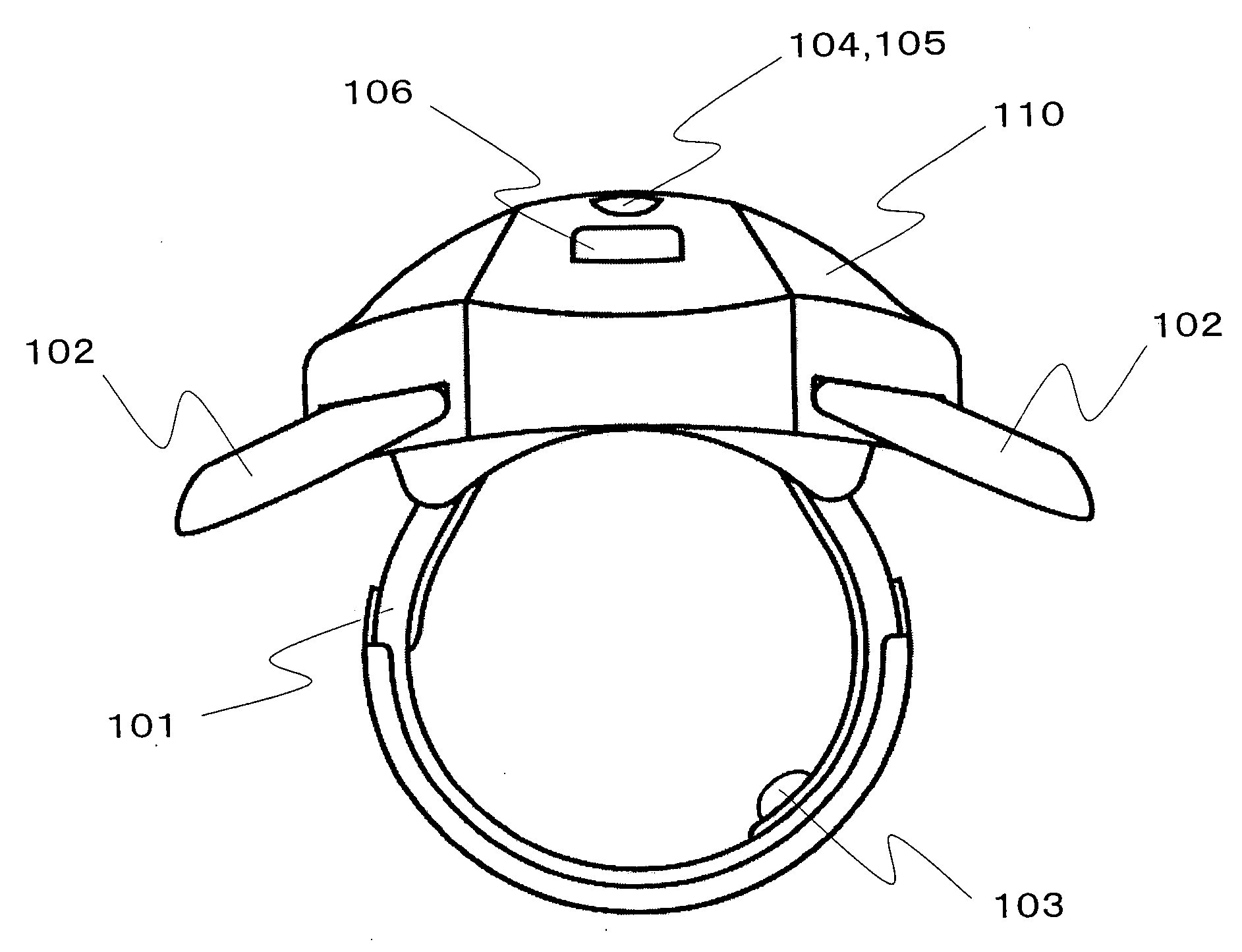
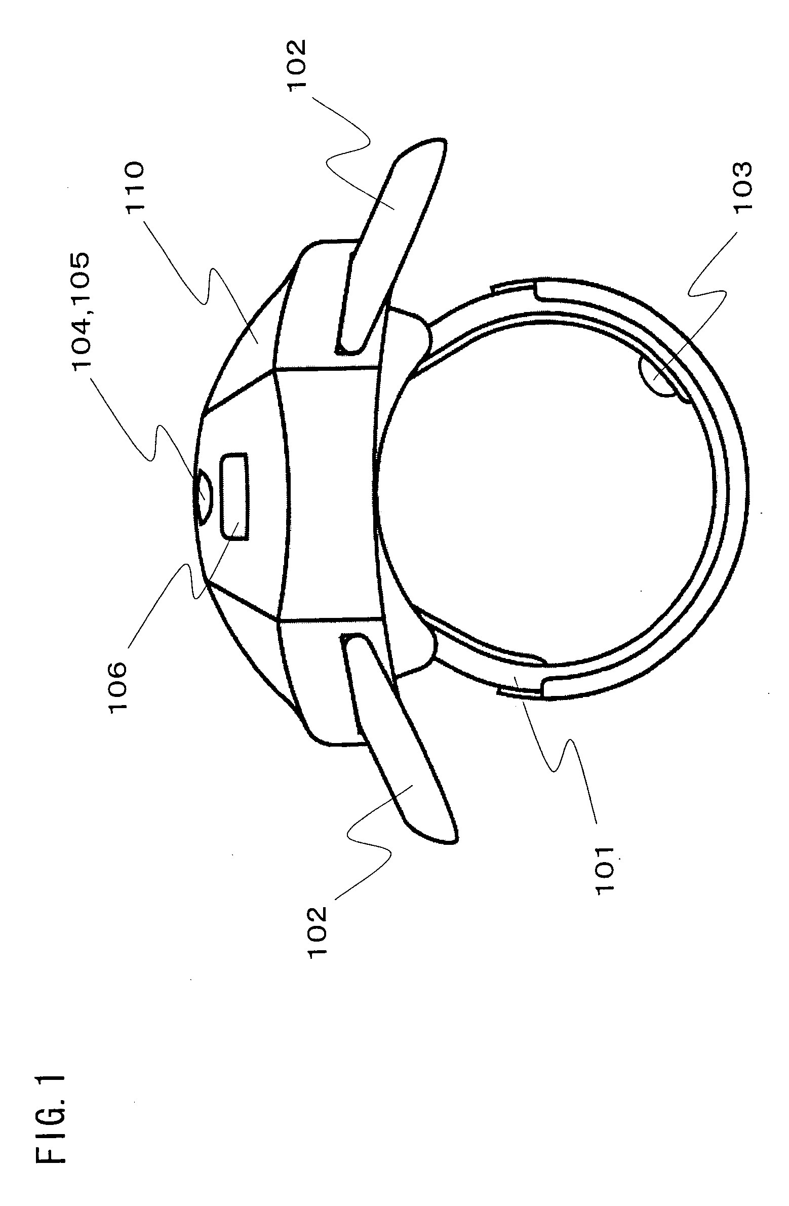
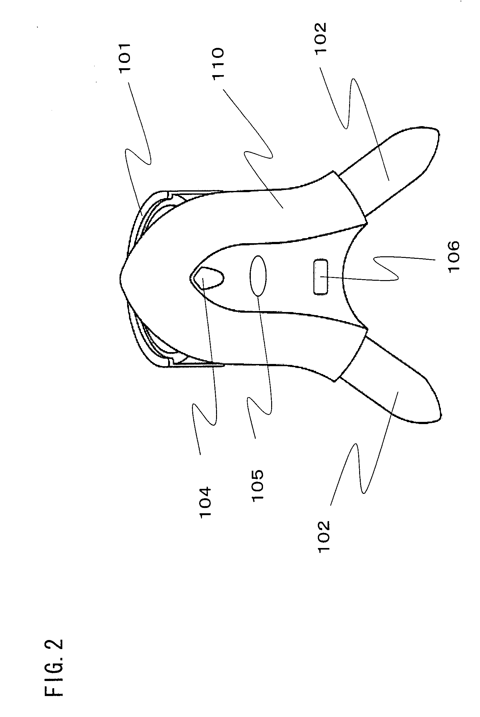
[0061]As an example of a circular or hyperbolic biological signal measurement device worn on a part of a human body, the following Embodiment 1 of the present invention describes a circular or hyperbolic ring-type biological signal measurement device (hereinafter, simply referred to as human-wearable sensor) which is worn on a finger for measuring a pulse wave and / or oxygen saturation. The human-wearable sensor is a device to be worn on a user's finger substantially at all time, and suitably measures pulsebeat, blood pressure, and even blood oxygen saturation from a pulse wave.

[0062]Through the above-described principal, the human-wearable sensor of the present embodiment measures a biological signal regarding ...

embodiment 2

[0110]FIG. 13 shows a cross-sectional view of a human-wearable sensor 100 of Embodiment 2. As shown in FIG. 13, a pressure detecting section 201 is provided between a sensing section 103 and a fitting section 101, and measures a pressure applied to a part of a human body by the sensing section 103. As described, the pressure detecting section 201 functions as a measurement environment detecting section for detecting a measurement environment: i.e., a pressing force (pressure), applied by the sensing section 103. Note that, in the present embodiment, the pressure detecting section 201 is realized by a pressure sensor for directly measuring a pressure applied by the sensing section 103 in the vertical direction to the surface of the human body. There are various known technologies for the pressure sensor, and therefore no explanation is provided here regarding the structure of the pressure sensor.

[0111]FIG. 14 is a block diagram showing functional structure of the human-wearable senso...

embodiment 3

[0118]FIG. 16 is a cross-sectional view showing a human-wearable sensor 100 of Embodiment 3. As shown in FIG. 16, both ends of a pressure detecting section 201 are connected to the fitting section 101. In the present embodiment, the pressure detecting section 201 measures a tensile force generated by the fitting section 101, so as to indirectly measures a pressure applied to a part of a human body by the sensing section 103. There are various known technologies for a tensile force sensor, and therefore no explanation is provided here regarding the structure of the tensile force sensor. Here, if the fitting section 101 has a sufficient flexibility, a pressing force at the sensing section 103 and the tensile force detected by the tensile force sensor are linearly correlated to each other. Thus, by measuring the tensile force generated by the fitting section 101, the pressure applied to the part of the human body by the sensing section 103 is indirectly measured. Of course, the pressur...


PUM


Abstract

A biological signal measurement device includes: a circular or hyperbolic fitting section (101) to be worn on a part of a human body; a sensing section (103) which is provided to the fitting section (101), and senses a biological signal by being closely attached to a specific part of the human body; a measurement environment judging section for judging an environment for measuring the biological signal by using the sensing section (103); a measurement environment notifying section (104) for notifying a user of a judgment result, according to the result of judgment performed by the measurement environment judging section; and a measurement environment adjusting section (102) for adjusting the measurement environment of the sensing section (103). Thus, it is possible to provide a human-wearable biological signal measurement device that allows easier maintenance of suitable measurement conditions.

Description

TECHNICAL FIELD[0001]The present invention relates to a biological signal measurement device worn on a human body for measuring a pulse wave or blood oxygen saturation.BACKGROUND ART[0002]In recent years, there has been a demand for devices that allow easier measurement of biological signals (e.g. pulsebeat or oxygen saturation) for home care or preventive care in everyday life. That is, there is a demand for devices capable of conducting such measurement unnoticeably, without any constraint. Today, as an example of a biological signal measurement device which does not get in the way of doing something and which is advantageous in terms of portability, there is a ring-type biological signal measurement device wearable on a finger. Various structures have been suggested for such a ring-type biological signal measurement device to reduce measurement errors attributed to shifting of a measuring section from a targeted portion of a finger or rotation of the measuring section about the f...

Claims


Application Information

Patent Timeline
Patent Type & Authority Applications(United States)
IPC IPC(8): A61B5/00
CPCA61B5/02241A61B5/02422A61B5/14551A61B2560/0462A61B5/6826A61B5/6838A61B5/14552A61B5/7221
Inventor KAWAJIRI, MOMOEASHIHARA, KAZUHIKOICHIKAWA, YUHJINAKAGAWA, KATSUYA
Owner SHARP KK
Why Eureka
Try Eureka