Structure assembly

Inactive Publication Date: 2008-07-24
WORLDS APART LTD
View PDF0 Cites 25 Cited by
  • Summary
  • Abstract
  • Description
  • Claims
  • Application Information

AI Technical Summary

Benefits of technology

[0022]In one embodiment, the structure which is formed is a toy model of a type which can be used in a child's playhouse, for example. In an alternative embodiment, the structure is used as pet housing, such as a kennel. In a yet further embodiment, the structure can be used as an item of furniture and / or to provide storage facilities. In each case, it will be appreciated that the structure can be moved between storage and erected in-use conditions easily and efficiently without the need for special tools or any tools to be used. It is also found that the location of the edges of the respective panels in the connecting member and the provision of the connecting member along the length thereof provides sufficient rigidity so as to allow the structure, when in the in-use condition, to be used safely and successfully.
[0025]In one embodiment, the sheet material used for the panels is medium density fiber board (MDF) or could be any other suitable sheet material. The coating can be a plastics material applied to a planer surface thereof to seal the same and allow the application of printing inks to preferably be applied using a 4-color printing process. This allows detailed decorative printing to be achieved which, therefore, makes the overall appearance of that panel and the structure as a whole to be more closely related to the item depicted. For example, if the structure is a toy model, the item which the same is intended to depict, such as a sink, washing machine, cooker or the like, can be shown on the printed surface which forms the external surfaces of the structure when in the in-use form.
[0027]In a further aspect of the invention there is provided a toy model structure. The structure comprises a top, and one or more side walls depending downwardly from the top to support the top at a distance from a support surface, at least the side walls formed by panels, the panels selectively movable between a storage form in which at least some of the same are disconnected, and an erected in-use form, and wherein in the in-use form the panels are retained in the required configuration by connecting members. The connecting members include at least one arm having a channel for the reception of an edge of a panel therein to thereby retain the panel in position and locate the panel in an angular orientation with respect to a second panel with which the connecting member is connected or formed.
[0029]Thus, the structure can be moved between the erected and storage conditions without the need for tools to be used.

Problems solved by technology

With regard to these features, preassembled structures often are not attractive to a purchaser.
This can provide additional expense to the manufacturer and / or customer and, in some instances if the tool is lost, the item cannot thereafter be constructed.
Furthermore, if the structure is required to be disassembled for storage purposes, the repeated use of the fastening means can lead to the same becoming damaged and / or lost, thereby preventing the reassembly of the structure.
A further problem which is often experienced with this type of flat pack furniture is that the appearance of the structure, when formed, is affected by the use of the conventional fastening systems.
It can be difficult in many cases for the fastening means to be hidden from view in all instances.
Furthermore, the panels of sheet material which are used to form the items are often, at best, provided with a continuously and / or repeated patterned surface which, therefore, limits the type of decorative patterns which can be applied to the structure panel.
This can often restrict the attractiveness and use of the structure for both purchase and in subsequent use and, therefore, can limit sales of the same.

Method used


Image

  • Structure assembly
  • Structure assembly
  • Structure assembly

Examples


Embodiment Construction

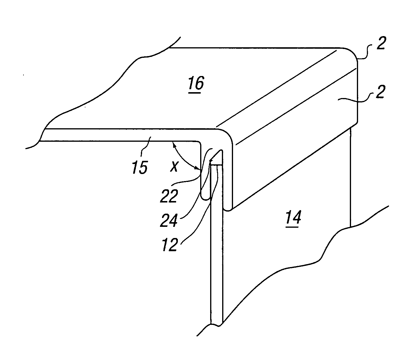
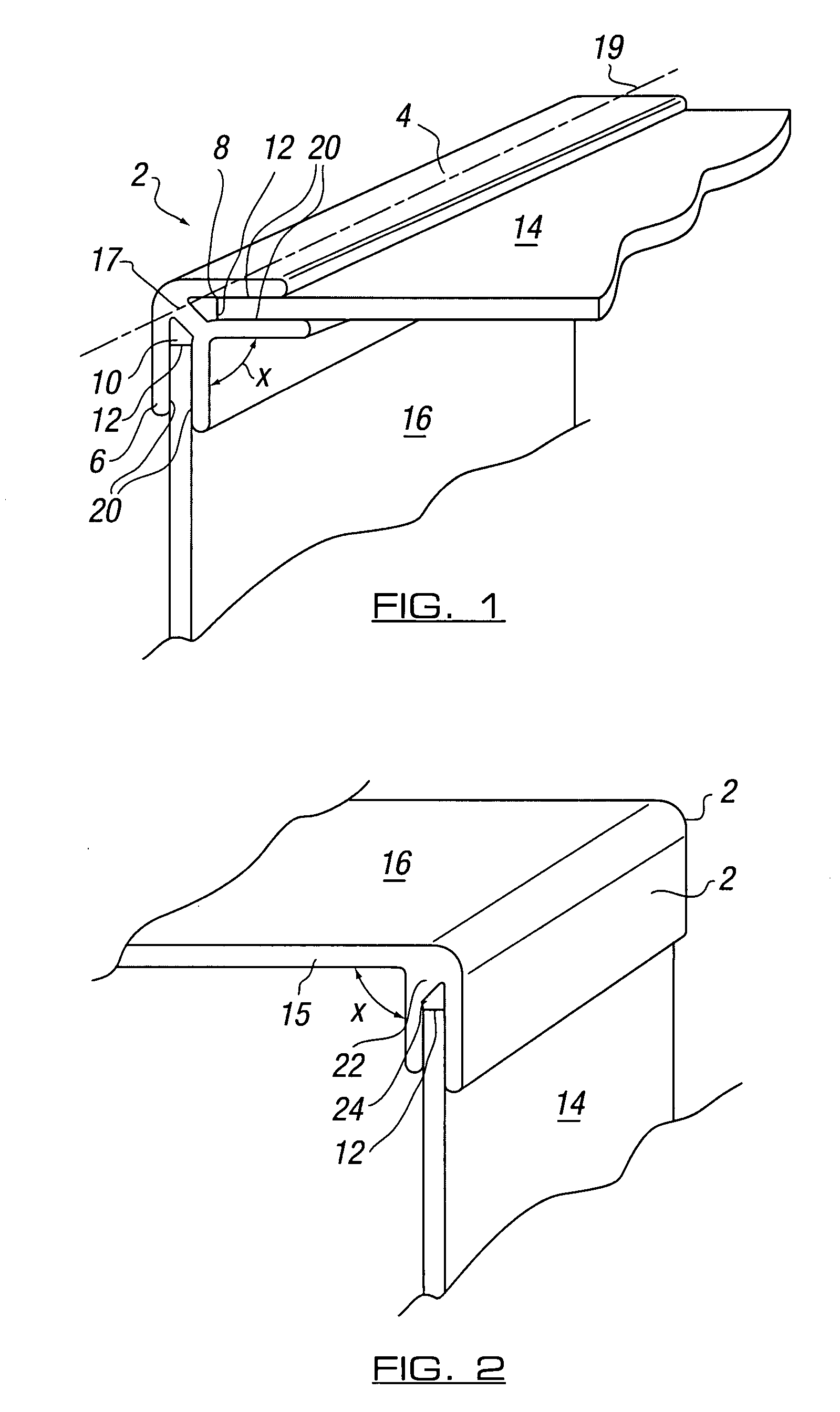
[0040]Referring now to FIG. 1, there is illustrated a connecting member 2 in accordance with one embodiment of the invention. As will be seen, the connecting member is elongate and, in this embodiment, includes first and second arms, 4, 6 which are angularly offset by an angle X, as illustrated. In this case, each of the arms includes a channel, 8, 10 respectively, which runs along the length of the same. The channel 8 of first arm 4 is shown receiving an edge 12 of a first panel 14 which is partially shown, and channel 10 of second arm 6 receives the edge 12 of a second panel 16 which is partially shown. The channels can be provided with retention means, which may be in the form of protrusions 20, which improve retention on one or more faces of the panel at the panel edge so as to improve retention of the panel within the channel. It will, therefore, be seen that by retaining the respective panel edges in the connecting member, the panels can be held in position and in position at ...


PUM


Abstract

The invention provides a structure that can be moved between storage and erected in-use forms via the use of one or more connecting members. The connecting member can be provided with at least two angularly disposed arms, at least one of the arms provided to receive an edge of a panel of the structure in the erected form. The other arms may receive an edge of another panel or may be formed integrally with a further panel. The structure can be moved between forms without the need for tools.

Description

CROSS REFERENCE TO RELATED APPLICATIONS[0001]This United States Application claims priority to British Patent Application No. 0701218.0 filed 23 Jan. 2007.STATEMENT REGARDING FEDERALLY SPONSORED RESEARCH OR DEVELOPMENT[0002]Not ApplicableTHE NAMES OF THE PARTIES TO A JOINT RESEARCH AGREEMENT[0003]Not ApplicableINCORPORATION BY REFERENCE OF MATERIAL SUBMITTED ON A COMPACT DISC[0004]Not ApplicableBACKGROUND OF THE INVENTION[0005]The invention to which this application relates is to an improvement in structure assemblies, such as toys, pet housing, storage means, and the like, which can be constructed from a “flat pack” form to an in-use, erected form so as to allow the structure to thereafter be used. Typically, the structure can thereafter be moved between the two forms in a manner which can be performed by adults or children in a relatively simple manner and, preferably, without the need for any, or any special, tooling to be used.[0006]Conventionally in structures of this type, the...

Claims


Application Information

Patent Timeline
IPC IPC(8): E04B1/38
CPCA63H33/105A63H3/52
Inventor WU, RICHARD
Owner WORLDS APART LTD
Why Eureka
Try Eureka