Method for damping rear extension arm vibrations of rotorcraft and rotorcraft with a rear extension arm vibration damping device

a technology of rear extension arm and rear extension arm, which is applied in the direction of rotocraft, active noise reduction system, propeller, etc., can solve the problems of unintentional participation, vibration of the entire helicopter cell structure, vertical bouncing, etc., and achieve the effect of improving the vibration properties of the tail boom and greater flight comfor

Inactive Publication Date: 2008-07-24
AIRBUS OPERATIONS GMBH
View PDF16 Cites 14 Cited by
  • Summary
  • Abstract
  • Description
  • Claims
  • Application Information

AI Technical Summary

Benefits of technology

[0011]An object of the present invention is to provide an effective method for damping tail boom vibrations of rotary-wing aircraft as well as creating a rotary-wing aircraft, especially a helicopter, with improved tail boom vibration properties and thus greater flight comfort.
[0015]According to the invention, in order to achieve the damping effect, only elongations, only contractions or else both elongations and contractions can be introduced. These introduced out-of-phase strains lead to a deflection or strain of the tail boom or adjacent fuselage structures and adjacent add-on components (e.g. fuselage cell, horizontal tail unit, rudder unit, main rotor torque-compensation devices such as, for example, a tail rotor and its components, tail boom joints in case of collapsible tail booms, etc.) that is out-of-phase with respect to the tail boom vibrations in question. In this manner, the undesired induced tail boom vibrations or vibration amplitudes that can, in fact, be felt in the entire rotary-wing aircraft can be markedly reduced or entirely neutralized. Due to these achievable advantageous vibration damping effects, a significant improvement can be achieved in the comfort of the pilot and passengers on board the rotary-wing aircraft.
[0016]With the solution according to the invention, the damping effect—unlike with the state of the art—is not limited to a only certain vibration direction but, depending on the location and direction of the introduction, can fundamentally be used for virtually any vibration direction that might occur. Therefore, with the method according to the invention, for example, tail shake effects (lateral) as well as vertical bouncing effects (vertical) can be effectively damped. The damping of the individual types of vibration can take place independently of each other or else together or simultaneously. Moreover, of course, it is also possible to achieve a highly effective damping of tail boom vibrations that have an orientation other than that of tail shake or vertical bouncing. Thus, on the basis of the principle according to the invention, for example, torsional vibrations can likewise be damped. By the same token, the damping of correspondingly superimposed forms of vibration is possible. Consequently, with the method according to the invention, the structure damping of the tail boom and thus ultimately also the damping of the entire rotary-wing aircraft structure can be improved simply and effectively.
[0017]The positive effect of the method according to the invention can be achieved fundamentally independently of the material of the tail boom or of the fuselage structure of the rotary-wing aircraft as well as of any add-on components. In other words, for instance, it is possible to effectively damp vibrations of tail booms or of adjacent fuselage structures made of materials such as, for example, fiber composites, which tend to have poor inherent damping properties. The method according to the invention even allows the damping of very large and highly rigid aeronautic structures. The method according to the invention can fundamentally be used for any type of rotary-wing aircraft or helicopter. Moreover, it is relatively simple in terms of its construction and can be produced with comparatively simple equipment, as will be explained below in greater detail.

Problems solved by technology

Although the development of modern helicopters involves extensive numerical flow simulations and wind tunnel experiments, undesired tail boom vibrations often occur in actual practice that cause the entire helicopter cell structure to vibrate or that can be felt throughout the entire helicopter.
Vertical bouncing is caused especially by turbulence excitation and control feedback, possibly with the unintentional participation of the pilot.
So far, in spite of intensive efforts on the part of the technical community, it has not yet been possible to reliably predict the interaction between the aerodynamics and the helicopter structure.
All of these vibrations affect flight control in a very negative manner, but they are not primarily a safety-relevant problem.
As a result, these effects have a detrimental impact on the pilots in particular but also on the passengers, considerably diminishing comfort or even impairing performance.
However, this solution turned out to have rather limited usefulness in terms of the attainable tail boom damping properties.
A drawback here turned out to be, on the one hand, the additional weight introduced into the overall system by the additional passive damping elements and, on the other hand, their quite limited effectiveness.
Consequently, the desired technical success could not be achieved with any of these approaches.
However, this method and this helicopter construction have not proven to be successful.
On the one hand, only the tail shake effect can be damped with this method and on the other hand, the tail rotor is only effective to a limited extent for damping purposes and, in particular, it is also much too slow.
Furthermore, a tail rotor is a highly safety-relevant component that should not be used for other purposes since the failure of such a safety-relevant system can greatly jeopardize the flight properties of the helicopter and thus the overall safety.
Consequently, this solution has proven to be disadvantageous.

Method used


Image

  • Method for damping rear extension arm vibrations of rotorcraft and rotorcraft with a rear extension arm vibration damping device
  • Method for damping rear extension arm vibrations of rotorcraft and rotorcraft with a rear extension arm vibration damping device
  • Method for damping rear extension arm vibrations of rotorcraft and rotorcraft with a rear extension arm vibration damping device

Examples


Embodiment Construction

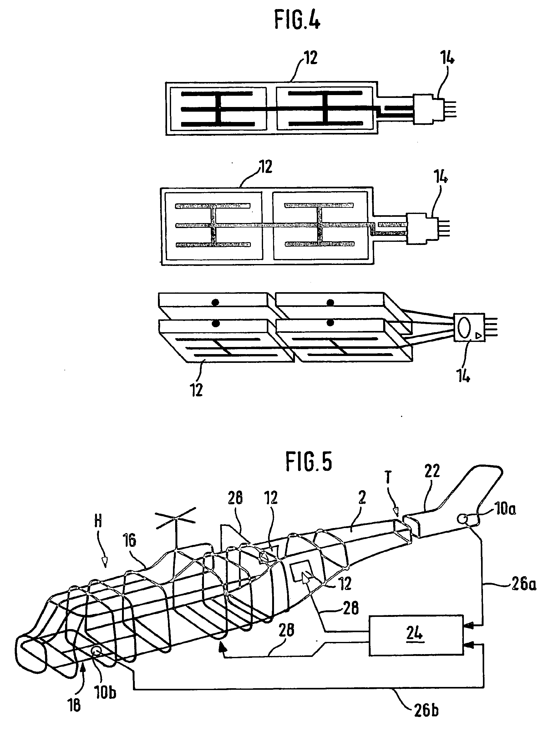
[0032]In order to avoid repetitions, in the description below and in the figures, the same parts and components are also designated with the same reference numerals as long as no differentiation is necessary.

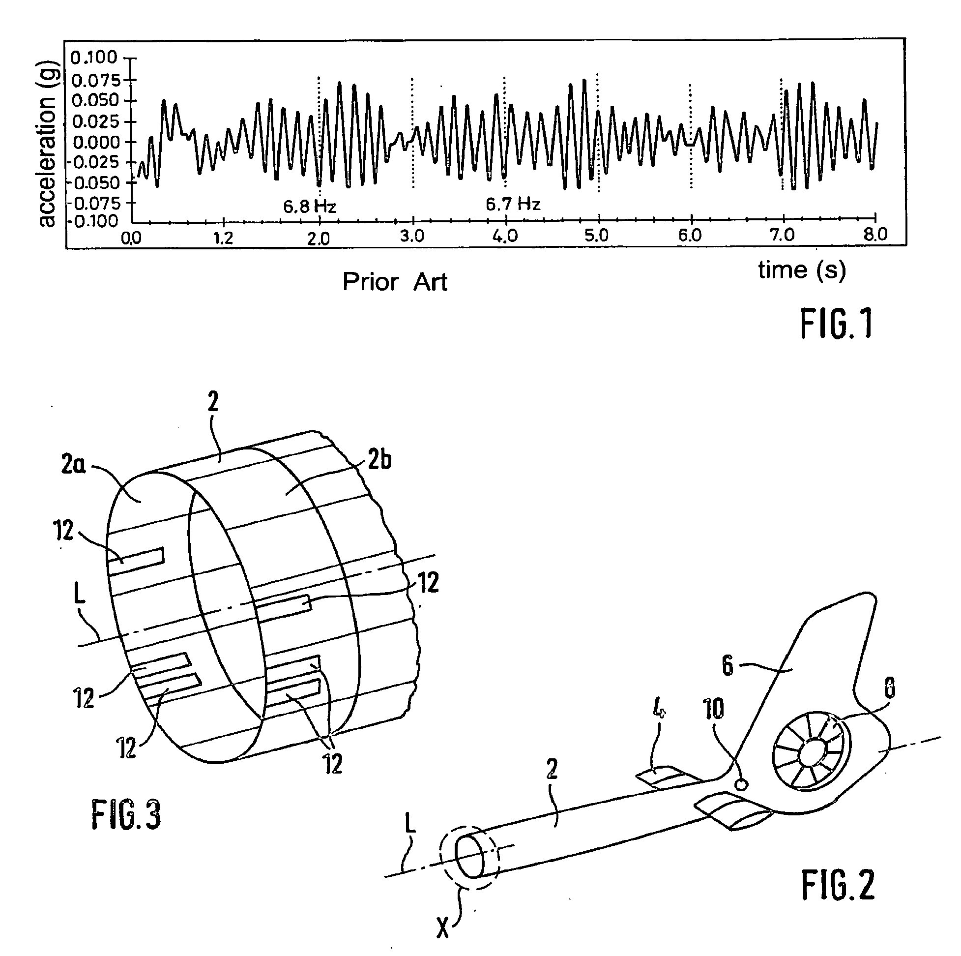
[0033]FIG. 2 shows a schematic perspective view of an essential area of a rotary-wing aircraft according to the invention in a first embodiment in order to illustrate a method according to the invention in a first embodiment. FIG. 3 shows a schematic enlarged view of the detail X from FIG. 2. In this case, the rotary-wing aircraft is a helicopter that has a fuselage with a main rotor and a drive means, a cockpit and passenger cabin area that is integrated into the fuselage as well as a tubular tail boom 2 that is arranged on the fuselage. The fuselage and the tail boom 2 are made essentially of fiber composite materials such as, for example, carbon fiber composite materials. For the sake of clarity, FIG. 2 shows only the tail boom 2 with its add-on components. In this case, thes...


PUM


Abstract

A method for damping vibrations in a tail boom of a rotary-wing aircraft includes the steps of detecting tail boom vibrations induced by external vibration excitation, and generating and introducing strains into the tail boom based on the detected tail boom vibrations. The strains are applied over a surface area and are out-of-phase with respect to the detected tail boom vibrations so as to damp the externally excited induced tail boom vibrations. In addition, a rotary-wing aircraft, includes a fuselage, a cockpit area integrated into the fuselage, a tail boom arranged on the fuselage and a tail boom vibration-damping device. The vibration-damping device has at least one sensor element configured to detect tail boom vibrations induced by external vibration excitation and at least one actuator configured to generate and introduce strains into the tail boom that are out-of-phase with respect to the induced tail boom vibrations, the actuator being functionally coupled to the sensor element, engaging with a tail boom structure at one side of the tail boom, and forming a flat-surfaced bond with the tail boom.

Description

[0001]The present invention relates to a method for damping tail boom vibrations of rotary-wing aircraft, especially helicopters, as well as a rotary-wing aircraft, especially a helicopter, with a tail boom vibration-damping device.BACKGROUND[0002]Aeronautic structures are increasingly being made of fiber composite materials for purposes of weight reduction. By nature, such structures are highly rigid and have a low inherent damping. This also applies, for example, to the tail booms of modern rotary-wing aircraft such as, for example, helicopters.[0003]Although the development of modern helicopters involves extensive numerical flow simulations and wind tunnel experiments, undesired tail boom vibrations often occur in actual practice that cause the entire helicopter cell structure to vibrate or that can be felt throughout the entire helicopter. The tail boom vibrations can generally be divided into two typical types of vibration or forms of vibration, which are referred to as “tail s...

Claims


Application Information

Patent Timeline
Patent Type & Authority Applications(United States)
IPC IPC(8): B64C27/00F16F15/02
CPCB64C27/001B64C2220/00F16F15/02B64C2027/8254
Inventor STREHLOW, HENNINGROTTMAYR, HEINERDUERR, JOHANNES K.ZAGLAUER, HELMUT W.
Owner AIRBUS OPERATIONS GMBH
Why Eureka
Try Eureka