Floor panel for forming a loading area in a cargo hold of an aircraft

Inactive Publication Date: 2008-07-24
AIRBUS OPERATIONS GMBH
View PDF71 Cites 17 Cited by
  • Summary
  • Abstract
  • Description
  • Claims
  • Application Information

AI Technical Summary

Benefits of technology

[0017]The geometry of the milled profiles may follow the geometrical shape of the so-called “beam of equal stress”. This results in the maximum achievable mechanical load-bearing capacity with minimal use of material.
[0018]To avoid damage to the floor panels in cases of very high local

Problems solved by technology

The floor construction is exposed, inter alia, to high mechanical loads caused by the cargo itself.
This is so since the floor panels have the task of transferring loads, for example from lashing points in the floor by way of shearing forces into the lateral connection to the skin of the fuselage cell, as a result of which their displaceability, and consequently their length, is limited.
On account of the required displacability of the floor panels to compensate for thermal expansions, the floor panels do not act as continuous beams, but can only be design

Method used


Image

  • Floor panel for forming a loading area in a cargo hold of an aircraft
  • Floor panel for forming a loading area in a cargo hold of an aircraft
  • Floor panel for forming a loading area in a cargo hold of an aircraft

Examples


Embodiment Construction

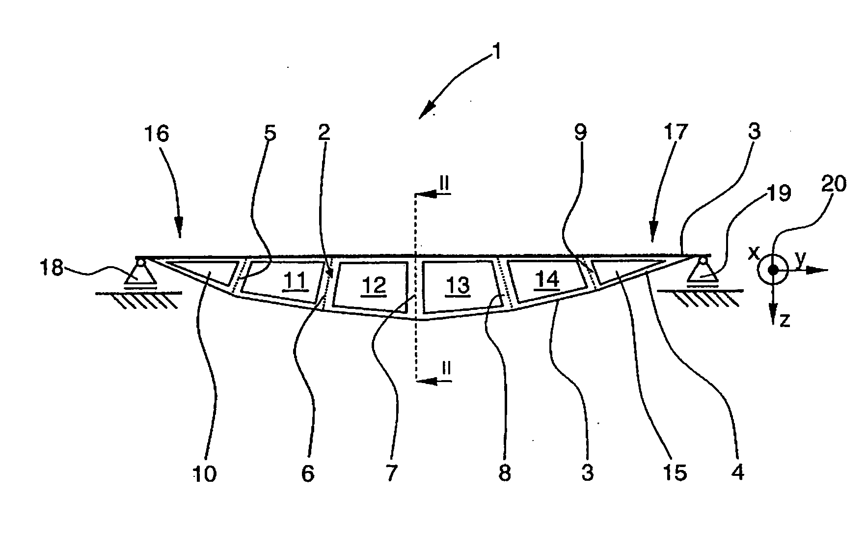
[0024]FIG. 1 shows a side view of a milled profile for forming the floor panel according to the invention.

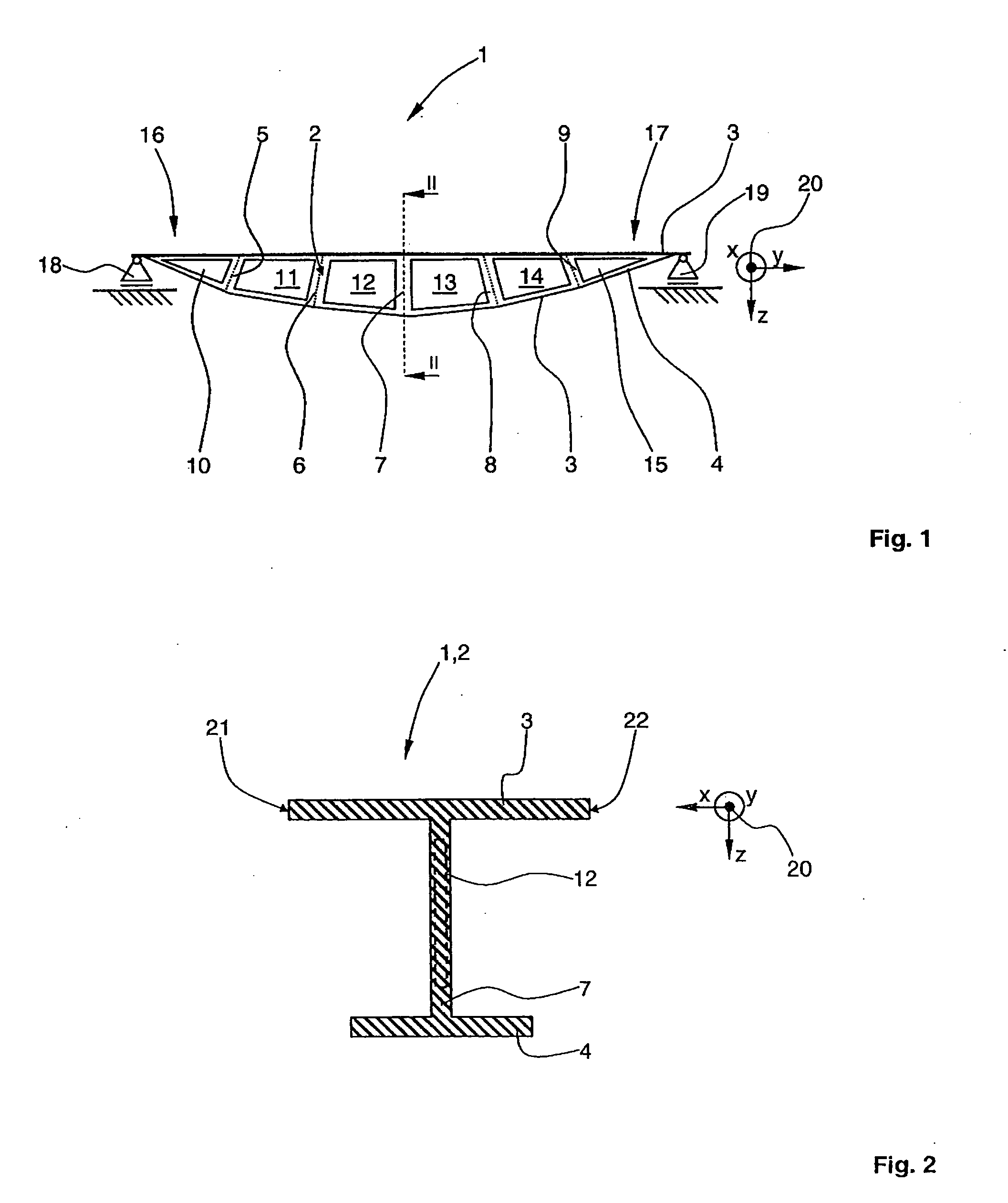
[0025]A milled profile 2, formed as a beam 1, for forming the floor panel according to the invention by arranging a plurality of such milled profiles one against the other along their longitudinal edges, comprises an upper flange 3 and a lower flange 4. The upper flange 3 has a straight geometry, whereas the lower flange 4 extends in an arcuate manner, at least in certain portions. Arranged between the upper flange 3 and the lower flange 4 are a plurality of webs 5 to 9, to achieve a defined spacing between the upper flange 3 and the lower flange 4 along their extent. Between the webs 5 to 9 there are six compartments 10 to 15. The compartments 10 to 15 are regions of the beam 1 that have been milled out completely from the beam 1 or just partially milled away, that is to say reduced in their material thickness.

[0026]The overall geometrical arrangement of the milled profile 2 mi...


PUM


Abstract

Disclosed is a floor panel, in particular for covering floors of cargo holds of aircraft. The floor panel is formed by a plurality of milled profiles, which are friction stir welded in each case along their longitudinal edges, with preference continuously to form longitudinal (butt) seams. The milled profiles each form a beam “of equal stress”, with an upper flange and a lower flange which are spaced apart from one another along their extent. The milled profiles have in each case a double-T-shaped cross-sectional profile, the upper flanges and the lower flanges being respectively connected by webs. With preference, the milled profiles are milled out in one piece from solid material of a sufficiently tough aluminium alloy. The joining together of the floor panel including a plurality of milled profiles that are arranged in parallel and friction stir welded allows a high mechanical load-bearing capacity of the floor panel in comparison with conventional sandwich floor panels along with a comparatively low weight.

Description

CROSS-REFERENCE TO RELATED APPLICATIONS[0001]This application claims the benefit of U.S. Provisional Application No. 60 / 881,640, filed Jan. 22, 2007 and German Patent Application No. 10 2007 011 619.7, filed Mar. 9, 2007, the entire disclosures of which are herein incorporated by reference.FIELD OF THE INVENTION[0002]The invention relates to a floor panel for forming a substantially continuous loading area in a cargo hold of an aircraft, comprising a plurality of beams that are arranged next to one another and connected.BACKGROUND OF THE INVENTION[0003]The floor in aircraft, in particular in cargo aircraft, has to meet increased mechanical requirements. The generally substantially planar and continuous floor is formed by a plurality of floor panels adjoining one another.[0004]The floor construction is exposed, inter alia, to high mechanical loads caused by the cargo itself. High local surface pressures generally occur, caused by trolleys, the tyres of vehicles and dirt particles tha...

Claims


Application Information

Patent Timeline
IPC IPC(8): B64C1/20
CPCB60P7/0807B64D9/00Y02T50/46B64D9/003Y02T50/40
Inventor BENTHIEN, HERRMANN
Owner AIRBUS OPERATIONS GMBH
Why Eureka
Try Eureka