
Soft touch clamp actuation mechanism

Active Publication Date: 2008-07-24
ASM TECH SINGAPORE PTE LTD
View PDF6 Cites 0 Cited by
  • Summary
  • Abstract
  • Description
  • Claims
  • Application Information

AI Technical Summary

Benefits of technology

[0010]It is thus an object of the present invention to seek to provide an actuator which is capable of drivi

Problems solved by technology

There are several drawbacks of this design.
First, since the solenoid is a highly non-linear device, its force increases rapidly as the solenoid plate approaches the solenoid.
This leads to an undesirably high impact on the substrate during clamping.
Secondly, since the force falls off rapidly with an increase in the gap between the solenoid and solenoid plate, there is a limit to the stroke of the plate displacement and thus a limit to the range of thickness of substrates which can be clamped.
Thirdly, the prior art affords no active control during de-clamping, but has to depend upon the return spring.
This consumes part of the solenoid force, thus leading to a smaller clamping force than would have been possible without the spring.
Whilst such a design can avoid imparting too much impact onto the substrate during clamping, one problem is that the cylindrical voice coil motor that is used provides a relative lower clamping force than a solenoid of the same weight.
Thus, it is less effective in providing a high clamping force.

Method used


Image

  • Soft touch clamp actuation mechanism
  • Soft touch clamp actuation mechanism
  • Soft touch clamp actuation mechanism

Examples


Embodiment Construction

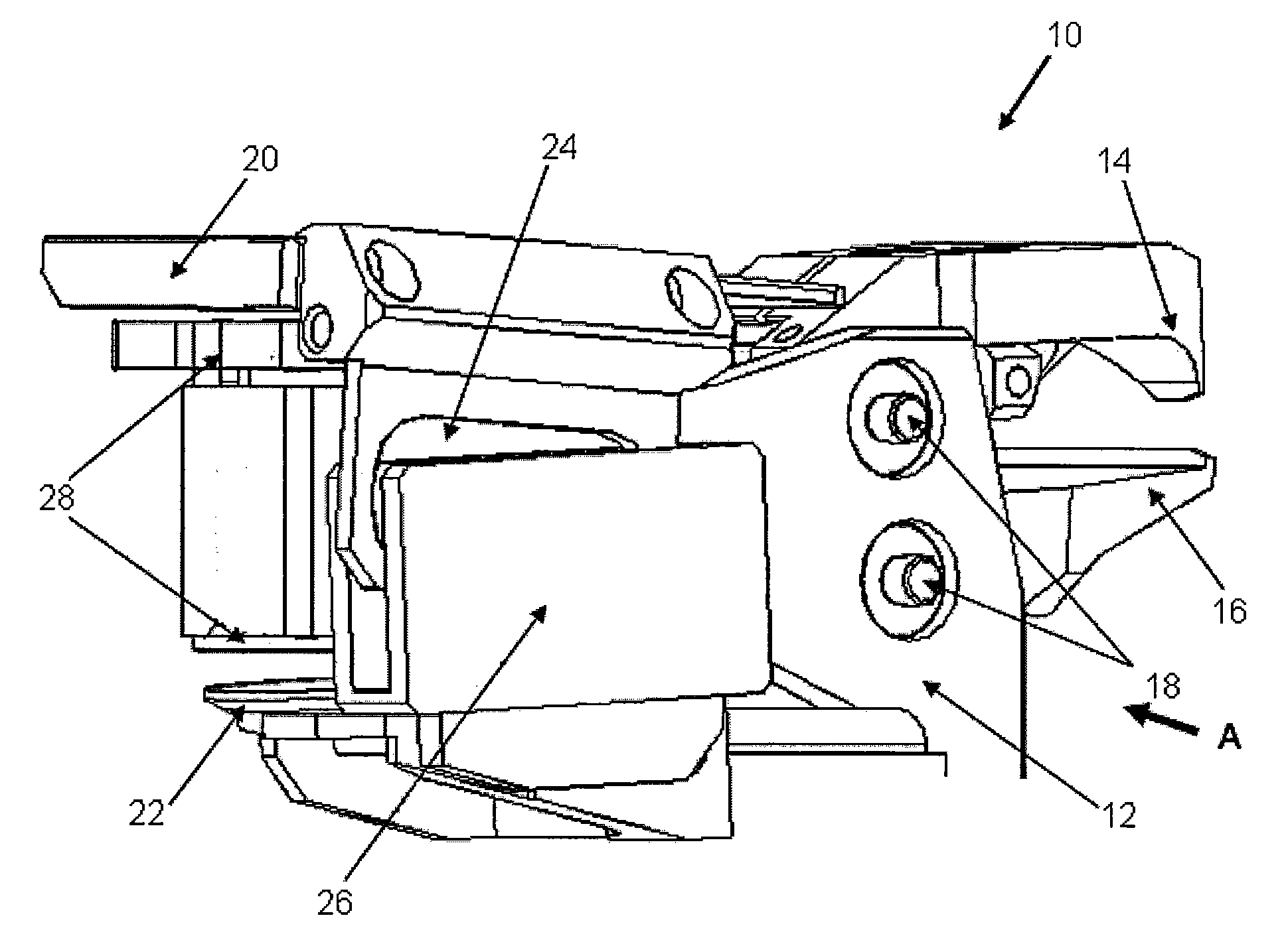
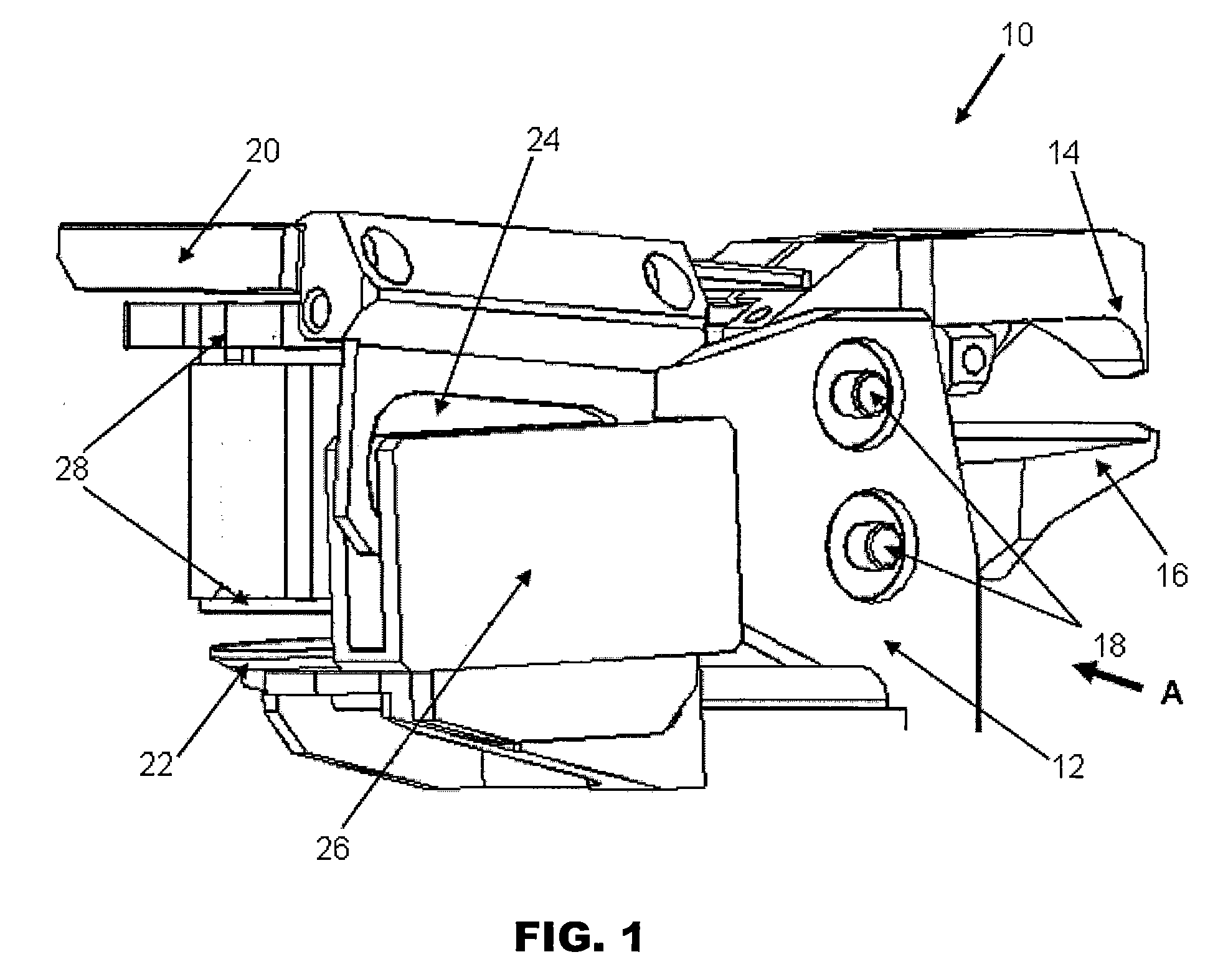
[0020]FIG. 1 is an isometric view of a clamping mechanism 10 according to the preferred embodiment of the invention. The clamping mechanism 10 has a support structure 12 and clamping jaws comprising an upper clamping jaw 14 and a lower clamping jaw 16 fixed onto the support structure 12. The upper and lower clamping jaws 14, 16 are pivotally mounted on the support structure 12 with pivots 18 so that they may rotate relative to the support structure 12 during opening and closing of the clamping mechanism 10.

[0021]The lower clamping jaw 16 is connected to a first solenoid pad, such as upper solenoid pad 20, and the upper clamping jaw is connected to a second solenoid pad, such as lower solenoid pad 22. The solenoid pads 20, 22 are operative to actuate opening and closing motion of the clamping jaws 14, 16. In a case where only one clamping jaw is movable and the other clamping jaw is fixed, only one solenoid pad would be required.

[0022]The upper and lower solenoid pads 20, 22 are attr...


PUM


Abstract

A clamping mechanism having clamping jaws is provided for holding an object. The clamping mechanism comprises a solenoid pad connected to at least one of the clamping jaws which is operative to actuate movement of the clamping jaw, and a solenoid motor that is operative to attract the solenoid pad towards it when it is energized. Further, a voice coil motor is rigidly coupled to the solenoid pad to drive the solenoid pad in directions towards or away from the solenoid motor.

Description

FIELD OF THE INVENTION[0001]The invention relates to a clamping mechanism including gripping jaws for holding an object, such as a substrate of an electronic device, so as to position it.BACKGROUND AND PRIOR ART[0002]In back-end semiconductor assembly processes, thermosonic ball bonding is by far the most demanding. To make an interconnect between a semiconductor device (commonly called “die”) and its substrate (“leadframe”), very thin wire, commonly gold wire of between 20 to 75 microns in diameter, is bonded, first onto a pad on the die and then onto the corresponding lead of the lead-frame on which the die is mounted. This process continues until all the pads and corresponding leads are connected. One leadframe may have anywhere from less than ten to a few tens of dies. In order to bring successive dies into a bonding area, a linear indexing system (“indexer”), is often used to index the leadframe with high precision. The indexer may essentially comprise a horizontal linear motor...

Claims


Application Information

Patent Timeline
IPC IPC(8): B66C1/42
CPCB25B5/06B25B11/002H01L24/85H01L2224/78703H01L2924/01079H01L2224/85H01L2924/00014H01L2224/45144H01L2924/00H01L2224/48H01L24/45H01L2224/45015H01L2924/20752H01L2924/20753H01L2924/20755H01L2924/20756H01L2924/00015H01L2924/20757H01L2924/20754H01L2924/2075H01L2224/05599
Inventor KWAN, KA SHING KENNYHE, TINGYU
Owner ASM TECH SINGAPORE PTE LTD
Learn More