Biometric piezo scanner

a piezoelectric film and biometric technology, applied in the field of fingerprint scanning and imaging, can solve the problems of reducing the durability of fingerprint scanners, increasing manufacturing and maintenance costs, and adding to the overall cost of fingerprint scanners

Inactive Publication Date: 2008-07-24
SONAVATION INC
View PDF91 Cites 100 Cited by
  • Summary
  • Abstract
  • Description
  • Claims
  • Application Information

AI Technical Summary

Benefits of technology

[0013]Other reflections indicative of additional biometrics related to the finger (e.g. from tissue, blood, bone, fingernail, etc.) can also be detected. A Doppler effect due to reflections from circulating blood can also be detected. Such a Doppler effect can provide further information about direction and speed of blood circulation.
[0014]According to another embodiment, an instantaneous pyroelectric effect can also be detected by the piezoelectric film sensor array to indicate a live finger presence. A signal indicative of the live finger detection can then be used to automatically initiate or “awaken” the fingerprint scanner to scan and capture an image of the fingerprint using the same piezoelectric scanner array.

Problems solved by technology

Such components add to the overall cost of a fingerprint scanner.
Mechanical structures to maintain alignment also increase manufacturing and maintenance costs.
This requires the silicon transducers to be thin, reducing their durability.
A silicon array with such a large size increases the base cost of a fingerprint scanner and leads to greater maintenance costs.
Durability and structural integrity are also more likely to suffer in such a large silicon geometry.

Method used


Image

  • Biometric piezo scanner
  • Biometric piezo scanner
  • Biometric piezo scanner

Examples


Embodiment Construction

1. Overview and Terminology

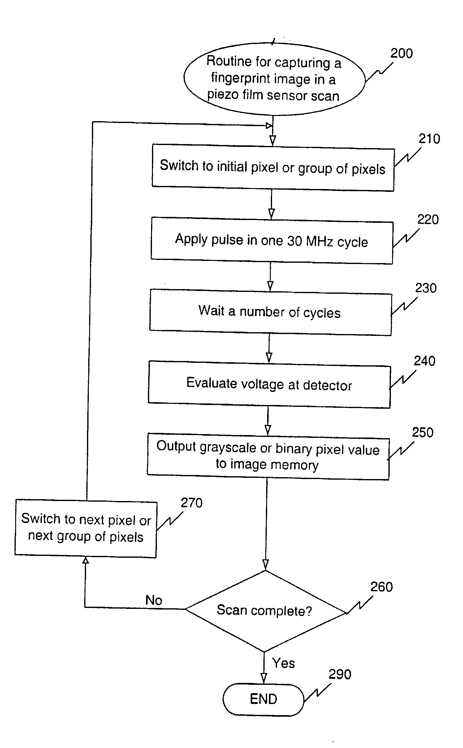
[0025]According to the present invention, a piezoelectric film biometric data sensing device is provided. The biometric sensing device can be, for example, a fingerprint scanner. A piezoelectric film sensor array is used to detect biometric data, for example, a fingerprint image.

[0026]The terms “piezoelectric” and “piezo” are used interchangeably herein to refer to the piezoelectric effect found in certain materials, including but not limited to piezoelectric polymer materials.

[0027]The term “conductor grid” as used herein is meant to refer to a pattern of conductors and includes, for example, a plurality of conductors arranged in parallel.

2. Piezoelectric Film Sensor Array

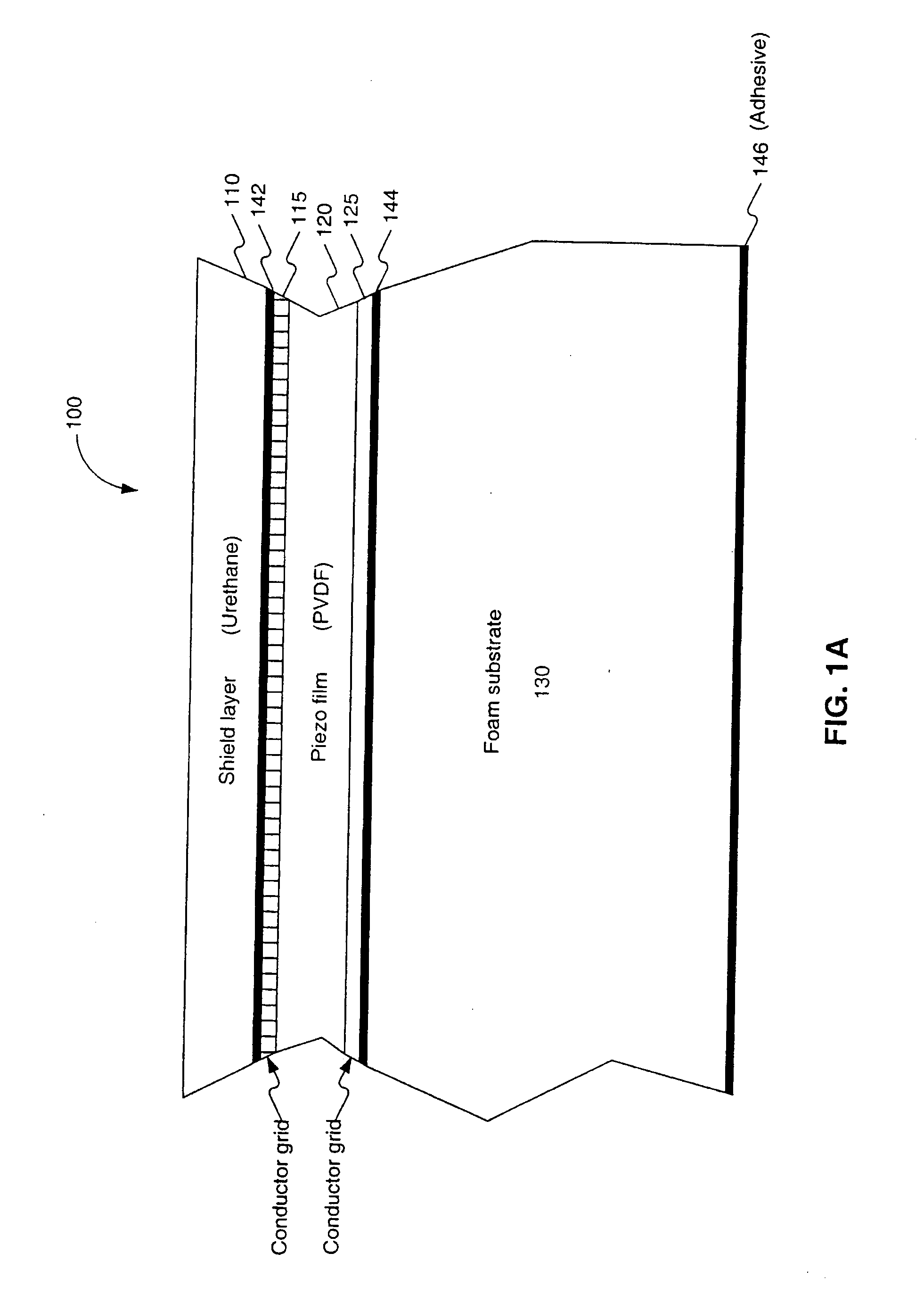
[0028]FIG. 1A is a cross-sectional view of a piezoelectric film sensor array 100 according to one embodiment of the present invention. Piezoelectric film sensor array 100 is a multi-layer structure that includes a piezo film 120 sandwiched between two conductor grids 115, 125. Piezo film...


PUM


Abstract

A piezoelectric thin film sensor array is used to scan and capture biometric data, for example, a fingerprint image. In one embodiment, a multi-layer structure includes a PVDF layer in between two conductor grids arranged orthogonally to one another. Urethane can be added to one side where a finger is placed. A foam substrate can be used as a support. In one feature, the PVDF, and grids can be peeled off like a label for easy replacement. Multiplexers are switched to scan the sensor. A single pixel or a group of pixels can be detected and output to an image memory. The presence of a fingerprint ridge is detected by virtue of a ring-down oscillation that arises from reflection when an electric field is applied to the piezoelectric thin film sensor array at a pixel in contact with the fingerprint ridge. For example, such a ring-down value associated with a fingerprint ridge can be detected at about 150 ns. (or 5 cycles at 30 MHZ). Other reflections indicative of additional biometrics (e.g. from tissue, blood, bone, fingernail, etc.) can also be detected. A Doppler effect due to reflections from circulating blood can also be detected. Such a Doppler effect can provide further information about direction and speed of blood circulation. An instantaneous pyroelectric effect can also be detected to indicate a live finger presence.

Description

[0001]This application claims the benefit of the filing date of U.S. Provisional Application Ser. No. 60 / 147,497, filed 9 Aug. 1999, which is hereby incorporated by reference in its entirety.BACKGROUND OF THE INVENTION[0002]1. Field of the Invention[0003]The present invention relates generally to fingerprint scanning and imaging. More specifically, this invention relates to a piezoelectric film used within a fingerprint scanner.[0004]2. Related Art[0005]Biometrics are a group of technologies that provide a high level of security. Fingerprint capture and recognition is an important biometric technology. Law enforcement, banking, voting, and other industries increasingly rely upon fingerprints as a biometric to recognize or verify identity. See, Biometrics Explained, v. 2.0, G. Roethenbaugh, International Computer Society Assn. Carlisle, Pa. 1998, pages 1-34 (incorporated herein by reference in its entirety). A number of companies are currently active in biometric finger technologies....

Claims


Application Information

Patent Timeline
Patent Type & Authority Applications(United States)
IPC IPC(8): G06K9/00A61B5/117G01B7/28A61B8/06G06T1/00
CPCA61B8/06G06K9/00899G06K9/00053G06K9/0002G06V40/1329G06V40/1306G06V40/40G06F18/00
Inventor SCOTT, WALTER G.
Owner SONAVATION INC
Why Eureka
Try Eureka