Micro-adjustable differential screw assembly

a differential screw and screw technology, applied in the direction of shaping cutters, manufacturing tools, transportation and packaging, etc., can solve the problems of limited product range, high cost, and limited product bore per tool

Active Publication Date: 2008-07-24
KENNAMETAL INC
View PDF21 Cites 16 Cited by
  • Summary
  • Abstract
  • Description
  • Claims
  • Application Information

AI Technical Summary

Problems solved by technology

The difficulty with conventional screw mechanisms, however, is that when presented with a bore that has tolerance limits in the r

Method used


Image

  • Micro-adjustable differential screw assembly
  • Micro-adjustable differential screw assembly
  • Micro-adjustable differential screw assembly

Examples


Embodiment Construction

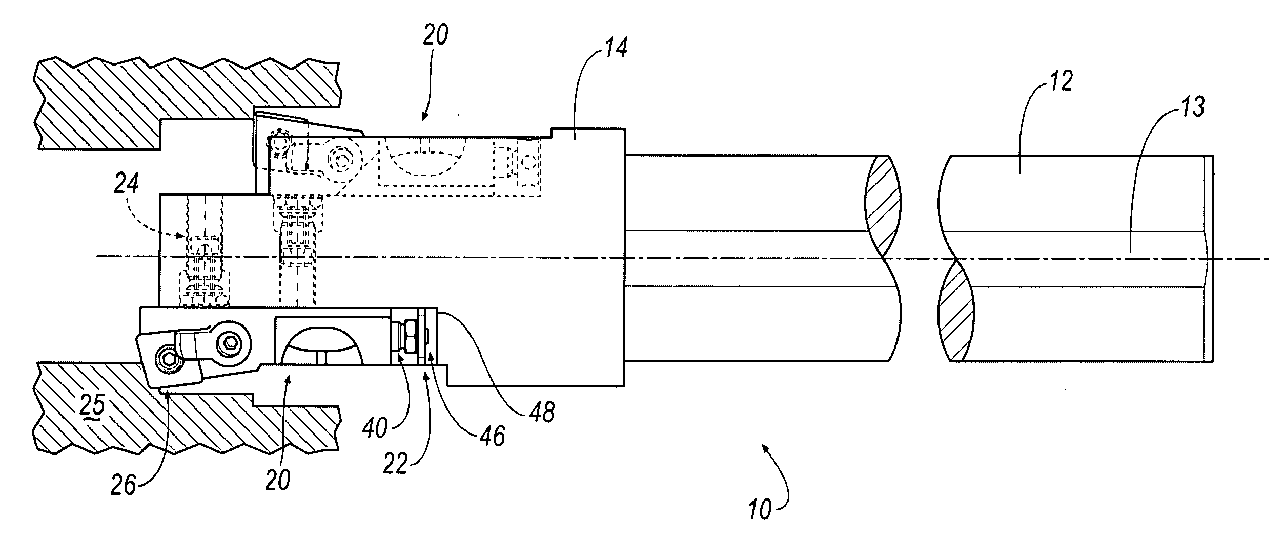
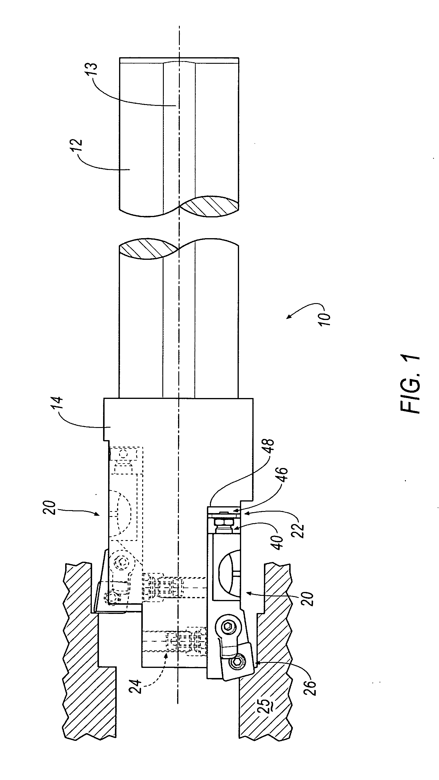
[0019]Referring now to FIG. 1, a boring bar 10 with one or more mounting cartridges 20 with micro-adjustable differential screw assemblies 22, 24 to perform a finish boring operation on holes within a workpiece 25 is shown according to an embodiment of the invention. Alternatively, the micro-adjustable screw assemblies 22, 24 can be mounted directly to the boring bar 10 without the need of the mounting cartridges 20. The boring bar 10 includes a shank portion 12 with a longitudinal axis 13 and having a diameter, for example, of approximately 1.50 inches, and a head portion 14 at which the boring or mounting cartridge(s) 20 are slidably and non-rotatably mounted thereto. In the illustrated embodiment, two substantially identical mounting cartridges 20 are shown, so only one mounting cartridge 20 will be described in detail below for brevity.

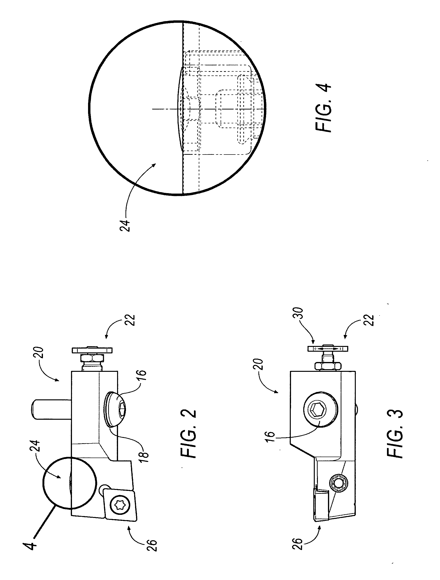
[0020]Referring now to FIGS. 2-4, each cartridge 20 includes an axial micro-adjustable differential screw assembly 22 (shown in phantom) for axia...


PUM

PropertyMeasurementUnit
Lengthaaaaaaaaaa
Lengthaaaaaaaaaa
Circumferenceaaaaaaaaaa

Abstract

A micro-adjustable differential screw assembly for providing fine adjustment of the axial and/or radial position of a cutting insert is disclosed. The micro-adjustable differential screw assembly can be mounted directly to a boring bar or to a mounting cartridge, which in turn, can be mounted to the boring bar. An axial micro-adjustable differential screw assembly provides fine adjustment of an axial position of the cutting insert, while a radial micro-adjustable differential screw assembly provides fine adjustment of a radial position of the cutting insert. The differential screw assembly includes a rotatable drive screw with threads of different thread pitches, and a non-rotatable adjusting screw with threads for mating with the drive screw. The difference in the thread pitches of the drive screw causes a greatly reduced axial and radial movement of the boring cartridge in relation to the relative movement of the drive screw, thereby providing fine adjustment in the axial and radial position of the cutting insert.

Description

BACKGROUND OF THE INVENTION[0001]Many devices exist in which a component must be positioned with extreme accuracy and the position adjusted from time to time. Such a component, for example, is a boring cartridge that is mounted on a boring tool. Screw mechanisms, such as differential screws or compound screws, are conventionally used to provide fine adjustment of the cutting insert to compensate for wear of the insert. By definition, a compound screw is a screw having on the same axis two or more screws with different pitch, or running in different directions (a right and left screw), and a differential screw is a compound screw by which a motion is produced equal to the difference of the motions of the component screws. The difficulty with conventional screw mechanisms, however, is that when presented with a bore that has tolerance limits in the range of plus or minus 0.0002 to 0.0030 inches, most products are limited to a single bore per tool and / or can be fairly expensive.[0002]T...

Claims


Application Information

Patent Timeline
IPC IPC(8): B23B51/00
CPCB23B29/0341B23B2260/004B23B2260/056Y10T408/8595Y10T407/1918Y10T408/8598Y10T408/86Y10T408/858
Inventor MUSIL, JOHN C.QUATKEMEYER, THOMAS P.
Owner KENNAMETAL INC
Why Eureka
Try Eureka