Impression cap

a technology of impression cap and impression plate, which is applied in the field of impression plate, can solve the problems of affecting the effect of impression plate,

Active Publication Date: 2008-07-24
STRAUMANN HLDG AG
View PDF9 Cites 25 Cited by
  • Summary
  • Abstract
  • Description
  • Claims
  • Application Information

AI Technical Summary

Benefits of technology

[0010]The aim of the present invention is therefore to provide an impression cap for producing the model of a dental implant which avoids the problems mentioned above.

Problems solved by technology

This conveying of the geometrical situation in the jaw onto a dental model, however, is extremely difficult, especially if the denture is positioned in the visible area, e.g. in the area of the front teeth, where aesthetic considerations are important.
Minor deviations of the geometry, e.g. due to vibrations during the setting process during imprinting, have negative effects on the prosthodontist's mold to be produced and thus also on the dental prosthesis.
Thus, impression caps adapted to the shape of the abutment are known which, however, have the disadvantage that the dentist must have a large number of impression caps in store for various geometries of the occlusal part of an abutment, in order to guarantee the precise adaptation to the abutment, since in case of exceedingly large clearances between the inner surface of the impression cap and the outer surface of the abutment's occlusal part, shifts of the impression cap can take place.
Clamping-type impression caps generally have flexible portions on the side facing the implant, which portions can clamp the dental implant; however, they are insufficiently secured against torsions since the clamping only acts on the collar area of the abutment, and therefore they easily slide off in the clamp connection area.
During manufacturing of such impression caps, it has been shown in practice that the production of an impression cap with the flexible portions provided on it for clamping or snapping onto the implant presents substantial problems during injection molding, since they must be manufactured with great precision.
Due to this required precision, these injection-molding model forms are costly to produce; and in addition, it has been shown that manufacturing of these thin-walled structures is extremely difficult.

Method used


Image

  • Impression cap
  • Impression cap
  • Impression cap

Examples


Embodiment Construction

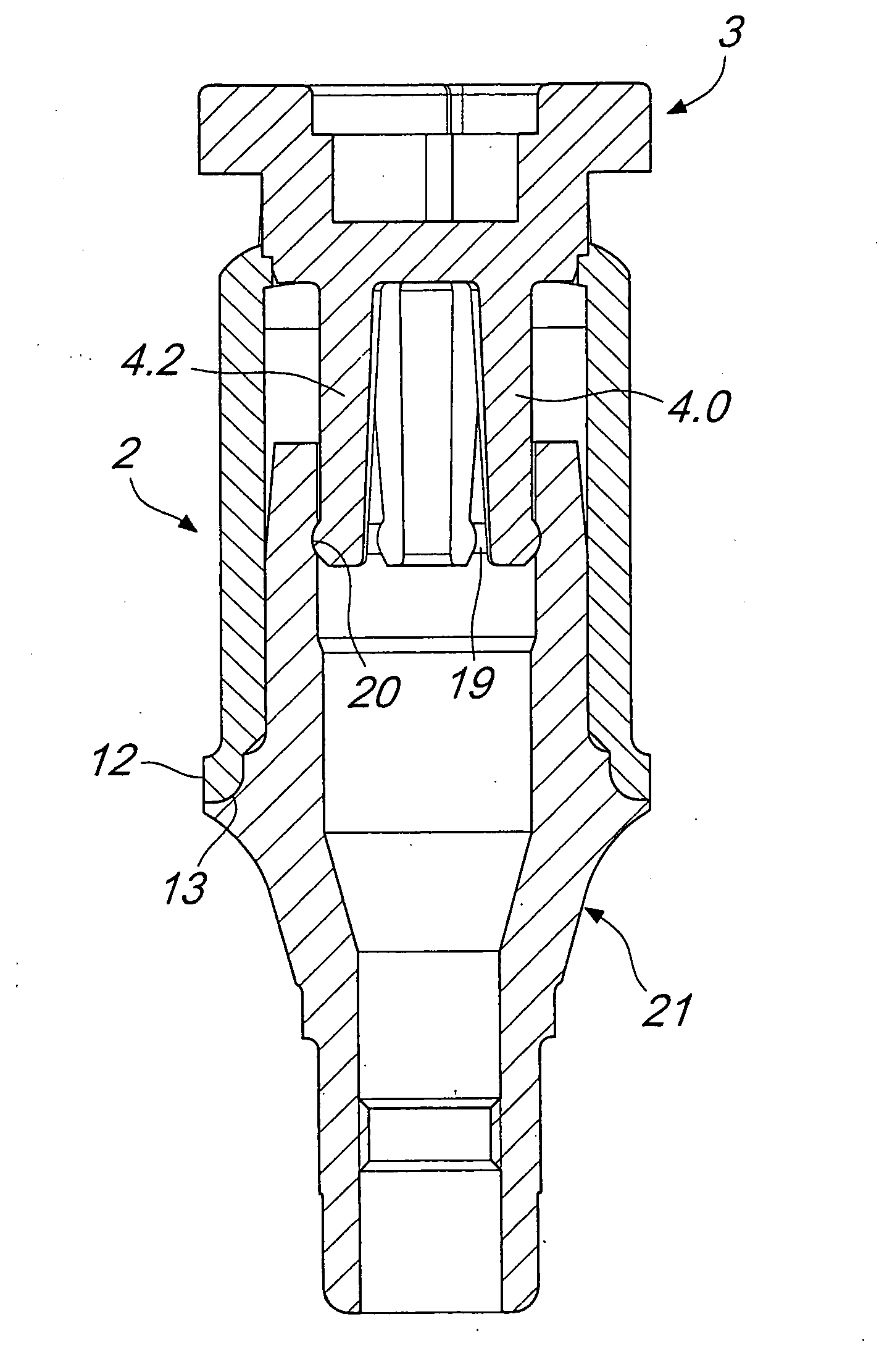
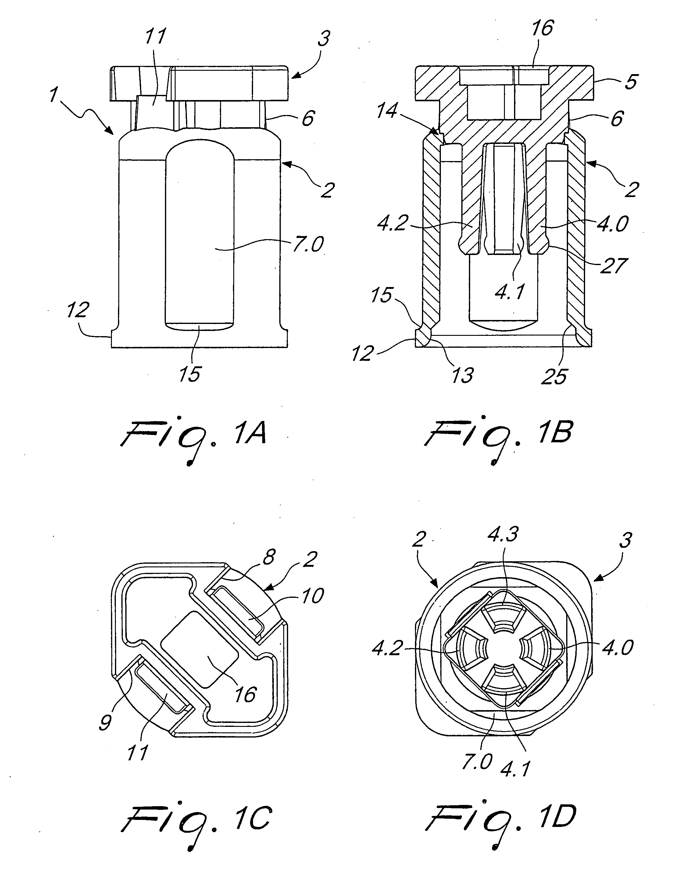
[0027]With reference to the FIGS. 1A through 4, a preferred embodiment of an impression cap is described. The impression cap 1 for manufacturing a model for a dental implant comprises a cylindrical body 2 and a cap-shaped part 3 which can be plugged onto the cylindrical body 2, the plug-on cap-shaped part 3 being provided with a plurality of fingers 4.0, 4.1, 4.2, 4.3 (in the following identified by reference number 4 for the sake of simplicity and also called elastic means), which engage the interior of the cylindrical body 2.

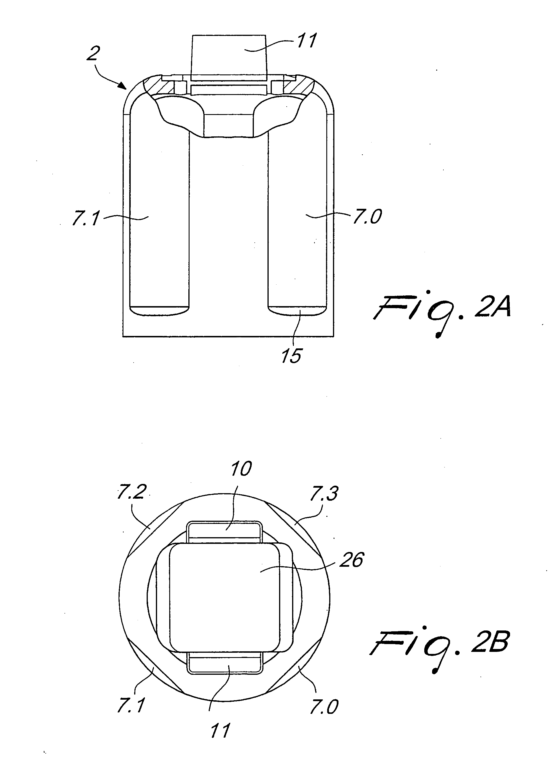
[0028]In the assembled condition, the upper cap-shaped part 3 protrudes through a square opening 26, see FIG. 2B, into the cylindrical body 2. The cap-shaped part 3 has a web portion 6 on which, in the assembled condition, elevations or protrusions 10, 11 of the cylindrical body 2 extend. In the assembled condition, the lower part of the web portion 6 touches a step-shaped portion 14 of the cylindrical body 2. For better stabilization of the two-part impressio...


PUM


Abstract

A two-part impression cap for manufacturing a model for a dental implant, comprising: a cylindrical body and a cap-shaped part pluggable onto the cylindrical body, the cylindrical body and the cap-shaped part having a common central axis, the cap-shaped part being provided with elastic elements extending in the direction of the central axis, which elements are adapted to be bent towards the central axis and thus to create a tension in the elastic elements for engaging a groove in the interior of an abutment, adapter or the like, and the cylindrical body being adapted to fit tightly on the outside of the abutment, adapter or the like.

Description

[0001]The present invention refers generally to a two-part impression cap for manufacturing a model for implants, in particular dental implants, which is easy and inexpensive to produce, and is flexible to use.BACKGROUND OF THE INVENTION[0002]For manufacturing an impression of the dental area, impression caps have become widely known in dentistry. They are used in the procedure for manufacturing a dental prosthesis, an imprint of a patient's dental positions becoming possible by means of these impression caps, which is true to nature and adapted to the position and direction.[0003]Dental implants are used to replace lost, damaged or unaesthetic teeth. This is done by means of an artificial dental prosthesis in order to restore the chewing ability or the aesthetic appeal within a patient's mouth.[0004]For manufacturing such a dental prosthesis, the dentist first places a dental implant in the jaw bone. After successful healing of the implant in the jaw bone, either an abutment or a d...

Claims


Application Information

Patent Timeline
Patent Type & Authority Applications(United States)
IPC IPC(8): A61C8/00
CPCA61C8/0001
Inventor SCHAUB, JORG
Owner STRAUMANN HLDG AG
Why Eureka
Try Eureka