Device and method for locking apparatuses

a technology of locking apparatus and device, which is applied in the direction of building locks, constructions, fastening means, etc., can solve the problems of high effort for replacing and fastening other apparatuses in the facility, and the screw connection between the apparatus feet and the frame stand is only accessible, so as to improve the locking of the apparatus and reduce the effort

Inactive Publication Date: 2008-07-31
LINDE AG
View PDF0 Cites 10 Cited by
  • Summary
  • Abstract
  • Description
  • Claims
  • Application Information

AI Technical Summary

Benefits of technology

[0007]The object of the present invention is to improve the locking of apparatuses in a frame stand and, in particular, to reduce the effort when replacing apparatuses.

Problems solved by technology

Depending on the compactness of the facility and the space conditions in and around the frame stand, the typically used screw connections between the apparatus feet and the frame stand are only accessible with difficulty or are also sometimes only accessible after removing other facility parts.
The effort for replacing and fastening other apparatuses in the facility may accordingly be high.

Method used


Image

  • Device and method for locking apparatuses
  • Device and method for locking apparatuses
  • Device and method for locking apparatuses

Examples


Embodiment Construction

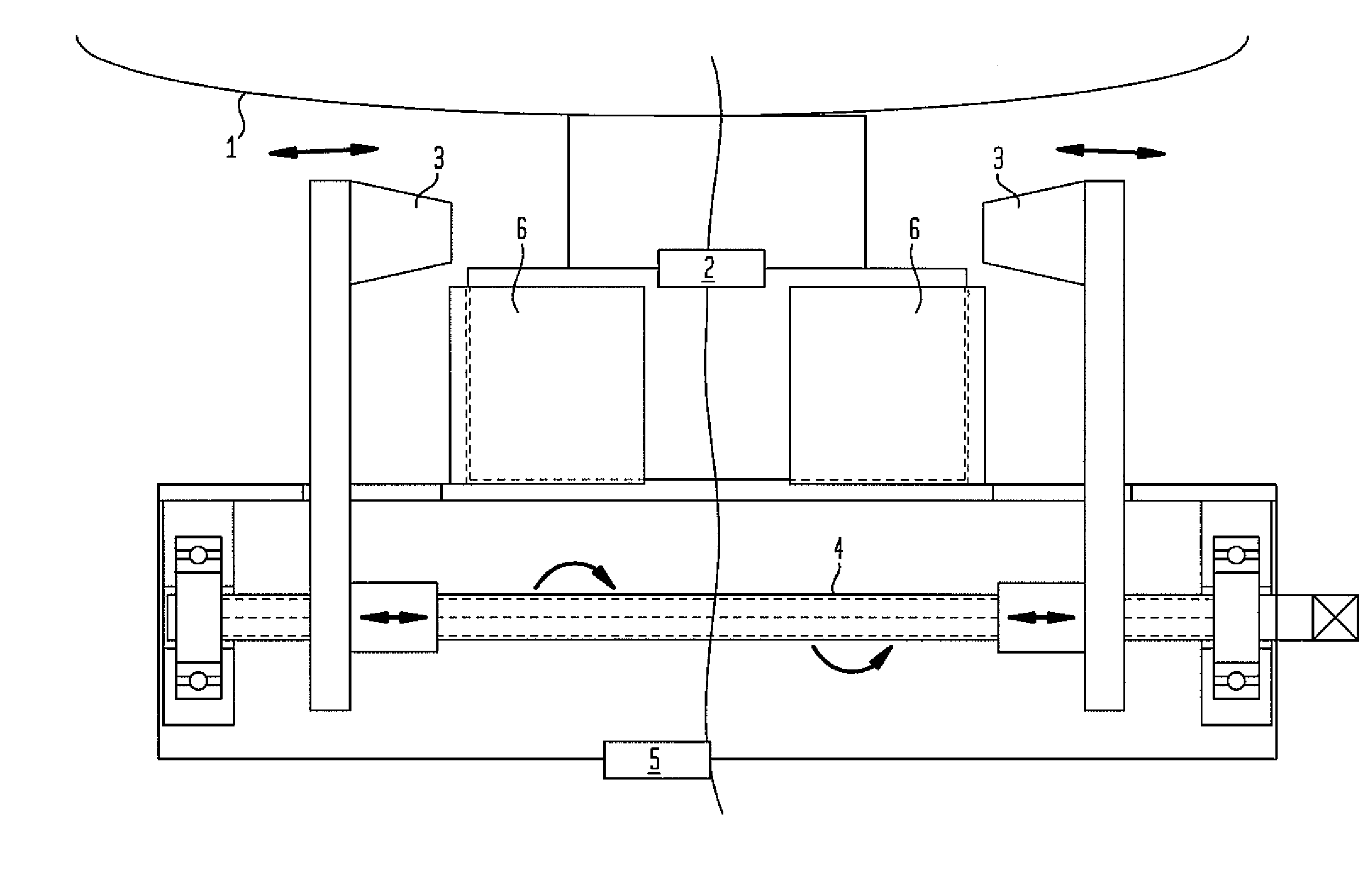
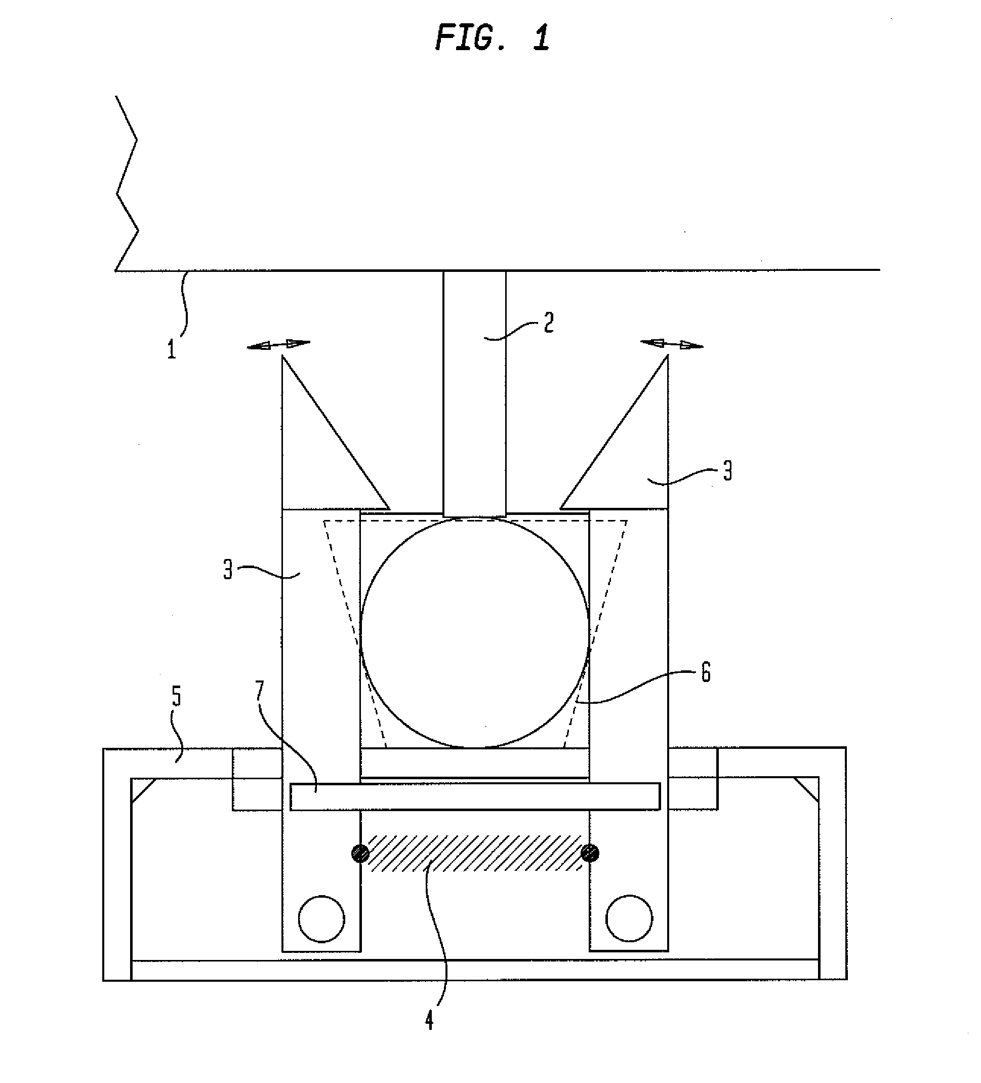
[0029]In FIG. 1, an apparatus 1 is shown as a detail, which rests on an apparatus foot 2. The apparatus foot 2 is locked by the locking hooks 3, which are in turn held in this position by the restoring unit 4. The apparatus foot 2 is received by so-called receptacles 6, which are fastened to the profile frame 5. The receptacles 6 are implemented in this example as receptacle corners 6. An unlocking slider 7 is available to disengage the locking. In this example, a restoring spring 4 is provided as the restoring unit 4.

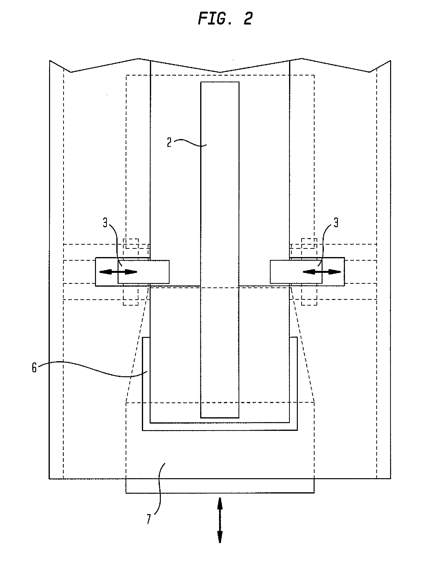
[0030]FIG. 2 shows a top view of the system according to the present invention, which is shown in FIG. 1 as a side view. The individual parts of the system are identified using the reference numerals from FIG. 1.

[0031]FIG. 3 shows a frontal view of a system according to the present invention having a modified restoring unit 4. The restoring unit 4 is implemented in this example as a trapezoidal thread 4 (½ right-handed, ½ left-handed thread). The remaining parts of the...


PUM


Abstract

The present invention relates to a system for locking apparatuses having a profile frame for receiving at least one apparatus. Furthermore, the present invention relates to a device for receiving one or more apparatuses, which has a profile frame, as well as a modified apparatus foot and a method for locking. The system according to the present invention is characterized in that the apparatus has apparatus feet modified for the engagement of a locking hook and the profile frame has at least one receptacle and at least one locking hook and one unlocking slider for each apparatus foot to be received, no screw connection parts used for locking the apparatus being provided.

Description

CROSS REFERENCE TO RELATED APPLICATIONS[0001]This application claims priority from German Patent Application Serial No. 102006061072.5, filed Dec. 22, 2006.BACKGROUND OF THE INVENTION[0002]The present invention relates to a system for locking apparatuses having a profile frame for receiving at least one apparatus. Furthermore, the present invention relates to a device for receiving one or more apparatuses, which has a profile frame, as well as a modified apparatus foot and a method for locking.[0003]A facility according to the method frequently has a frame stand, in which one or more apparatuses are introduced as components of the facility and screwed in place therein. The components of the facility may be, for example, heat exchangers, electric heaters, or containers together with valves and components of measurement and regulatory technology, as well as piping.[0004]The apparatuses are typically connected to the frame stand using screw connections. The apparatus feet are connected...

Claims


Application Information

Patent Timeline
Patent Type & Authority Applications(United States)
IPC IPC(8): E05B65/00
CPCF16B2/12F16B2/10Y10T70/50Y10T70/60
Inventor HIMMEN, HANS-RUDOLF
Owner LINDE AG
Why Eureka
Try Eureka