Transfer Switch With Generator Runtime Counter

a transfer switch and generator technology, applied in the field of transfer switches, can solve the problems of insufficient routine maintenance, inability to properly address the need for prompting proper routine maintenance, and only frequent inspection of gauges or other indicators mounted on such a generator power sour

Inactive Publication Date: 2008-07-31
EATON CORP
View PDF19 Cites 11 Cited by
  • Summary
  • Abstract
  • Description
  • Claims
  • Application Information

AI Technical Summary

Benefits of technology

[0009]In accordance with one aspect of the invention, a transfer switch is for a first power source, a second power source, and a load. The transfer switch comprises a power switching device structured to select between the first power source and the second power source and to supply power to the load, and a transfer control structured to monitor the second power source, to maintain a runtime count of the second power source, and to provide an indication of the runtime count.
[0010]In accordance with another aspect of the invention,

Problems solved by technology

However, due to the high level of noise and vibration, exhaust fumes and typically unsightly appearance of such generator power sources, it is commonplace to locate such a generator power source remotely from a structure to which such a generator power source provides power.
The simple fact that such a generator power source is located outside and away from such a structure typically results in gauges or other indicators mounted on such a generator power source being only infrequently chec

Method used


Image

  • Transfer Switch With Generator Runtime Counter
  • Transfer Switch With Generator Runtime Counter
  • Transfer Switch With Generator Runtime Counter

Examples


Embodiment Construction

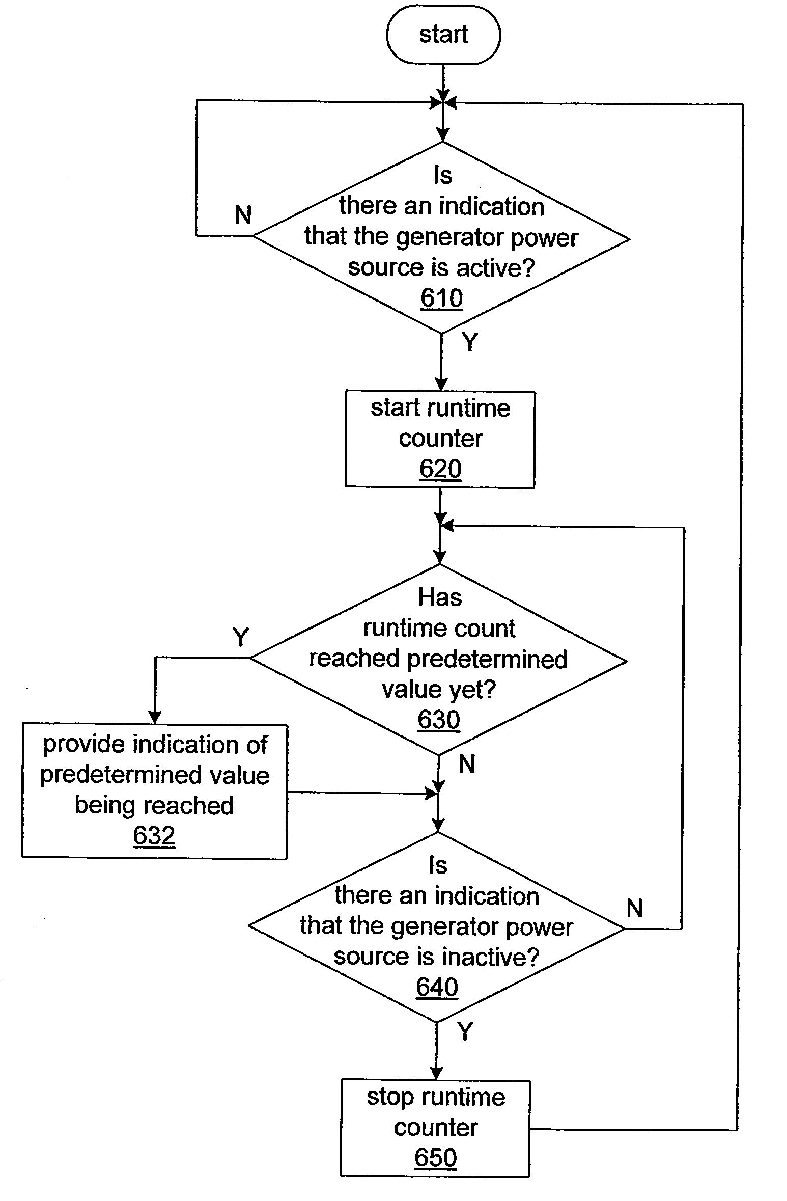
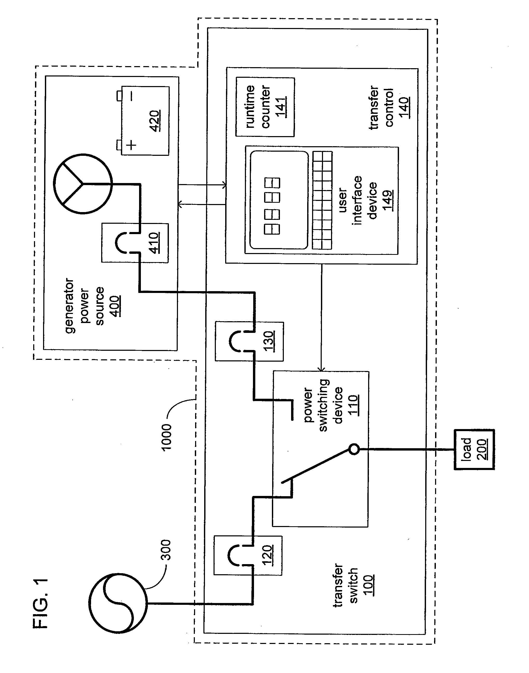
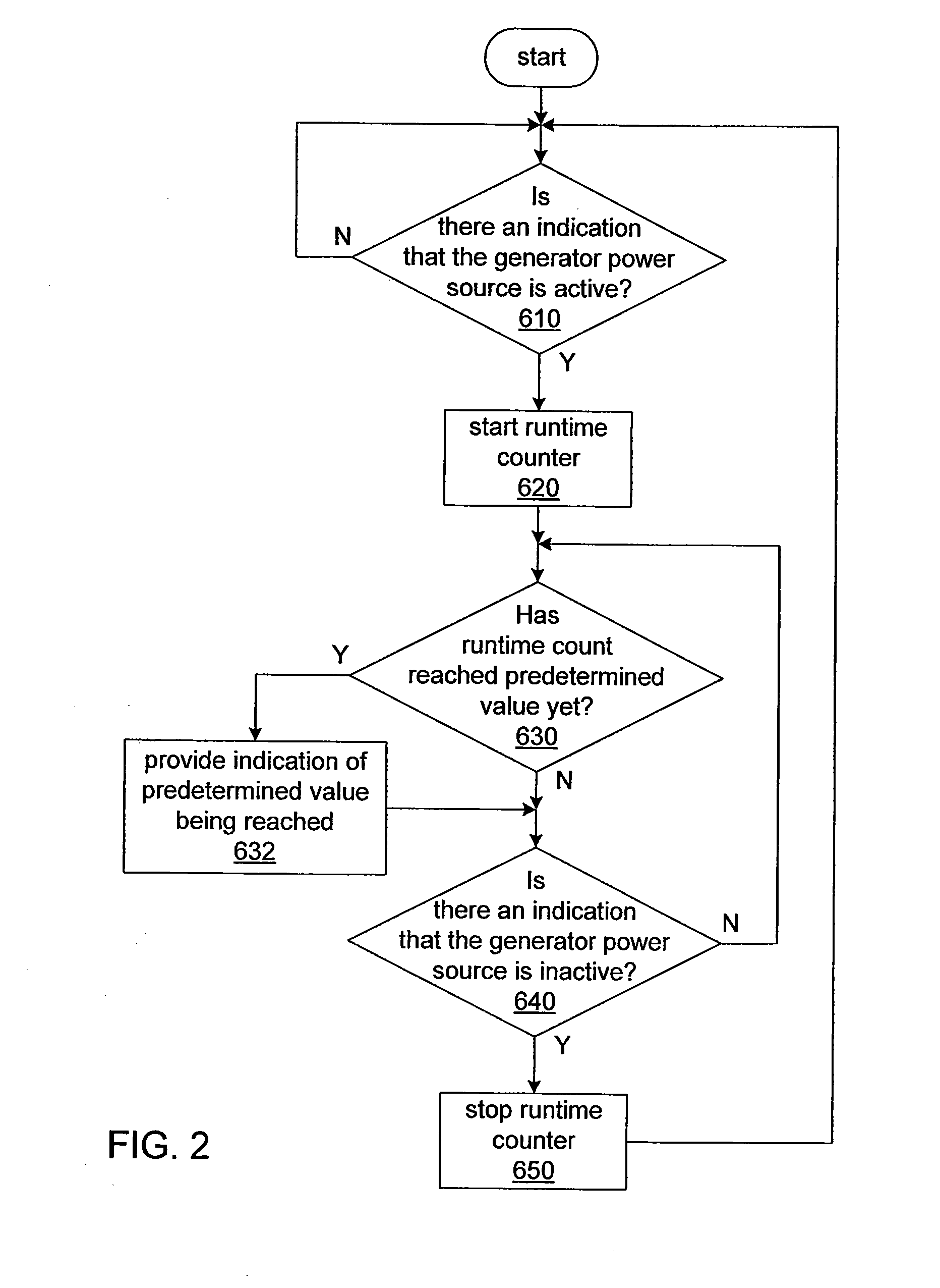
[0014]Referring to FIG. 1, a transfer switch installation 1000 to selectively provide electrical power to a load 200 from multiple alternate sources incorporates a generator power source 400 and a transfer switch 100 receiving electric power, at various times, from one or both of a utility power source 300 and the generator power source 400. The transfer switch 100 allows the source of electric power supplied to the load 200 to be switched between the utility power source 300 and the generator power source 400. The load 200 represents one or more electrical devices within, for example, a commercial or residential structure (not shown) that requires electric power, such as for example and without limitation, lighting, plug-ins, appliances, commercial machinery and climate control systems. The utility power source 300 is a source of electric power from a commercial vendor (e.g., without limitation, a connection to an electrical grid maintained by a utility power company).

[0015]The gen...


PUM


Abstract

An transfer switch having a transfer control provides electric power to a load. The transfer switch includes a power switching device provided with electric power from a first power source, such as a utility power source, and a second power source, such as a generator power source. The transfer control is structured to monitor the second power source, maintain a runtime count of the second power source, and provide an indication of the runtime count, either at the transfer switch or at a location remote from the transfer switch and the second power source.

Description

BACKGROUND OF THE INVENTION[0001]1. Field of the Invention[0002]This invention pertains generally to transfer switches and, more particularly, to transfer switches having an ability to monitor a generator power source. This invention also relates to methods for monitoring a generator power source.[0003]2. Background Information[0004]Transfer switches are employed in a wide variety of residential and commercial structures to allow an electrical load therein to be supplied with power from an alternate power source in the event of instability and / or loss of power from a main power source. A typical transfer switch installation allows an onsite backup electrical generator, serving as a generator power source, to supply electrical power in place of a utility power source on an occasion where the electrical power supplied by the utility power source has become unstable (e.g., as in the case of a brownout) or has failed, entirely.[0005]In the interests of ensuring reliable operation, such ...

Claims


Application Information

Patent Timeline
IPC IPC(8): H01H83/12H02J9/04
CPCH01H2300/018H02J2009/068H02J9/061H02J9/068
Inventor LATHROP, TODD MATTHEWHARTZEL, RONALD DALEPOPOVICH, BERT
Owner EATON CORP
Why Eureka
Try Eureka