Backlight control method for high dynamic range LCD

a backlight control and high dynamic range technology, applied in static indicating devices, instruments, cathode-ray tube indicators, etc., can solve the problems of image distortion in the detailed parts of the image obtained using these conventional backlight control methods, and the image distortion occurs with the increasing contras

Active Publication Date: 2008-07-31
AU OPTRONICS CORP
View PDF14 Cites 27 Cited by
  • Summary
  • Abstract
  • Description
  • Claims
  • Application Information

AI Technical Summary

Benefits of technology

[0006]According to an embodiment of the invention, the backlight control method first determines the gray level histogram in the pixels of an image. Afterwards, the histogram is accumulated to obtain a cumulative function of the image.

Problems solved by technology

However, because the backlight brightness is reduced, the image distortion occurs with the increasing contrast.
Nevertheles

Method used


Image

  • Backlight control method for high dynamic range LCD
  • Backlight control method for high dynamic range LCD
  • Backlight control method for high dynamic range LCD

Examples


Embodiment Construction

[0011]The present invention will be apparent from the following detailed description, which proceeds with reference to the accompanying drawings, wherein the same references relate to the same elements.

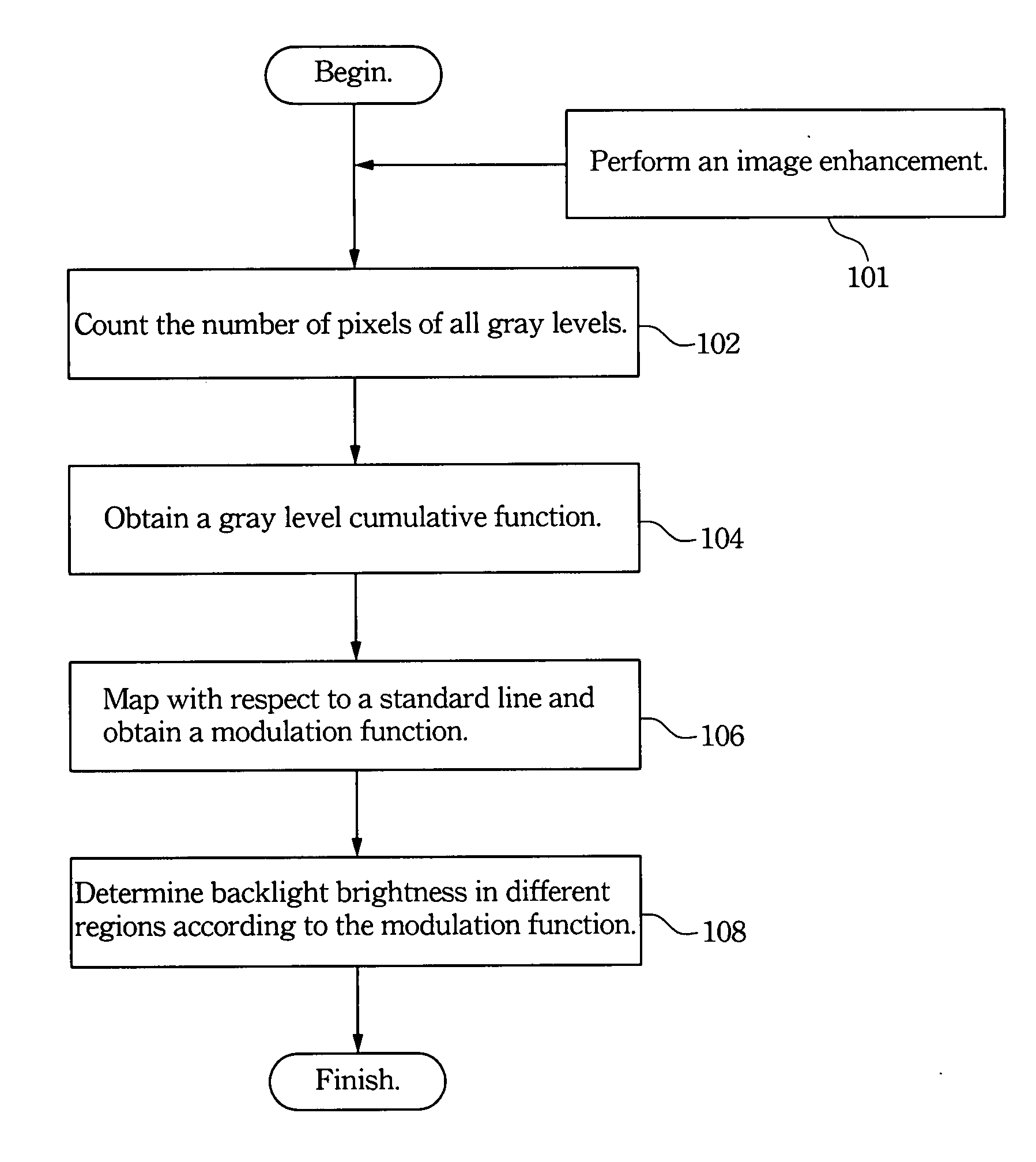
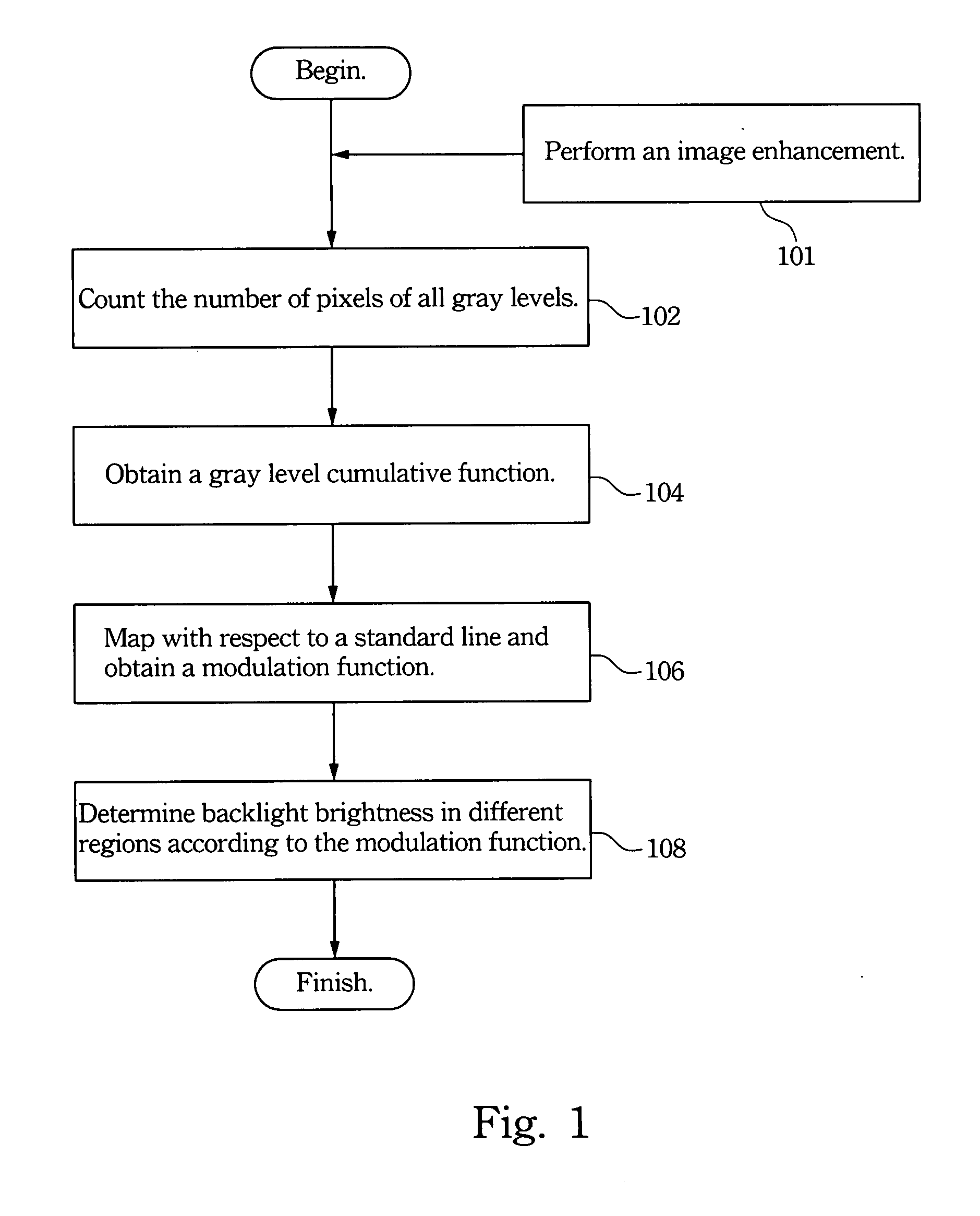
[0012]The backlight brightness in each region of an image is adjusted according to the properties thereof. In addition to merely enlarging the gray level difference between the highest and lowest ones in each region, the difference between adjacent gray levels is reduced. More explicitly, this embodiment uses a mapping function of the image as its basis. This function is mapped with respect to a standard line with an appropriate slope to obtain the backlight module function for the backlight brightness in different regions. In comparison with the two conventional backlight control methods in the prior art, the invention can highlight the details of an image.

[0013]As shown in FIG. 1, the method according to an embodiment of the invention first determines the histogram of gray levels in...


PUM


Abstract

A cumulative function of image is obtained according to its gray levels of pixels. This function is then mapped to obtain a backlight modulation function according to a reference line. The backlight brightness provided for different regions of the liquid crystal display are decided by the backlight modulation function while displaying the images.

Description

RELATED APPLICATIONS[0001]This application claims priority to Taiwan Application Serial Number 96103083, filed Jan. 26, 2007, which is herein incorporated by reference.BACKGROUND OF THE INVENTION[0002]1. Field of Invention[0003]The invention relates to a liquid crystal display (LCD) and, in particular, to a backlight control method for a high dynamic range LCD.[0004]2. Related Art[0005]Conventional high dynamic range display technology involves one light source, two modulators, and an optical structure between them and is used to control the backlight brightness in different regions of the display. By controlling the backlight brightness in each region, the high dynamic range display technology can increase the dynamic range or contrast of the display. However, because the backlight brightness is reduced, the image distortion occurs with the increasing contrast. Currently, there are two methods for determining the backlight brightness in each region. The first is to determine the ba...

Claims


Application Information

Patent Timeline
IPC IPC(8): G09G3/36
CPCG09G2320/0238G09G3/3406
Inventor LIN, FANG-CHENGLIAO, CHENG-YULIAO, LIN-YAOHUANG, YI-PAIWANG, TE-MEISHIEH, HAN-PING
Owner AU OPTRONICS CORP
Why Eureka
Try Eureka