Communication apparatus, KVM switch and communication control method

Inactive Publication Date: 2008-07-31
FUJITSU COMPONENENT LTD
View PDF4 Cites 4 Cited by
  • Summary
  • Abstract
  • Description
  • Claims
  • Application Information

AI Technical Summary

Benefits of technology

[0015]According to yet another aspect of the present invention, there is provided a communication control method in a KVM switch including: server units respectively connected to computers; user units respectively connected to input/output devices for transmitting signals to the computers and receiving signals from the computers; and a main unit that connects the server units and the user units, wherein each of the server units, user unit

Problems solved by technology

However, this change may cause some units to fail to communicate with each other.
For example, this problem often arises when different models of units are included in the KVM switch or different versions of units are included even when the units are of an identical model.
If there is a device having version mismatch, this device is inhibited from working.

Method used


Image

  • Communication apparatus, KVM switch and communication control method
  • Communication apparatus, KVM switch and communication control method
  • Communication apparatus, KVM switch and communication control method

Examples


first embodiment

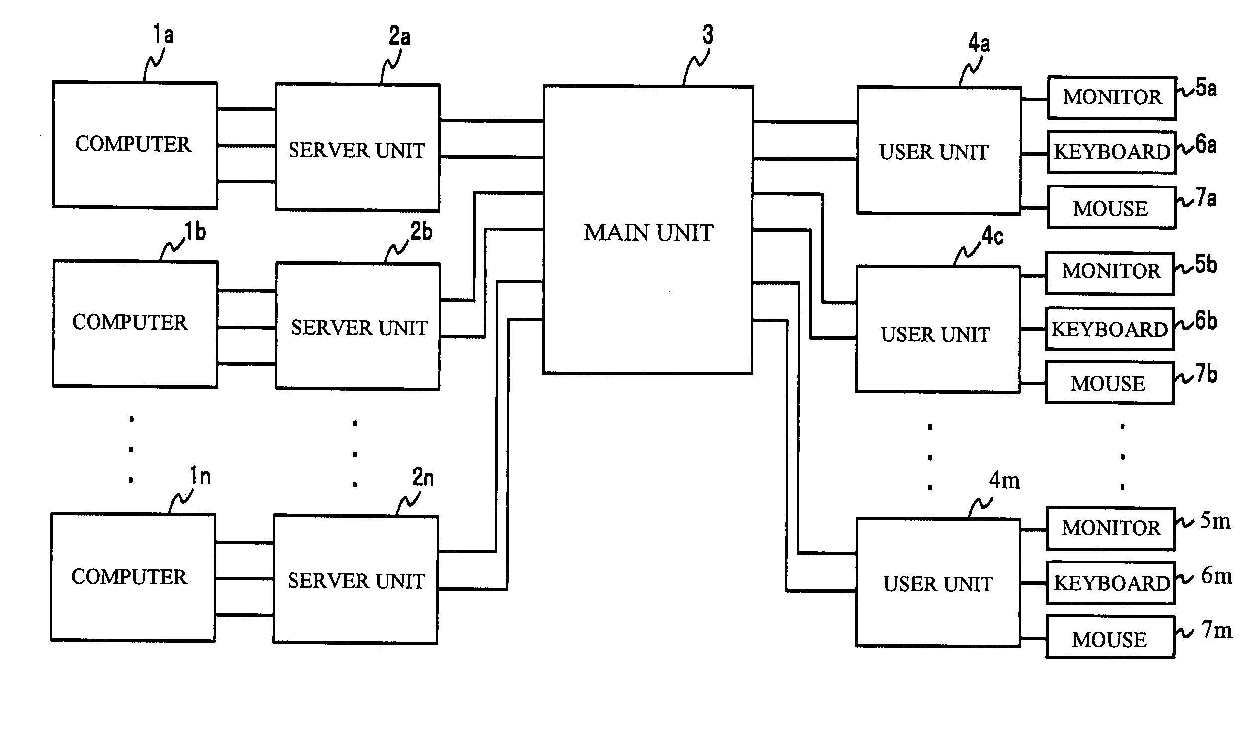
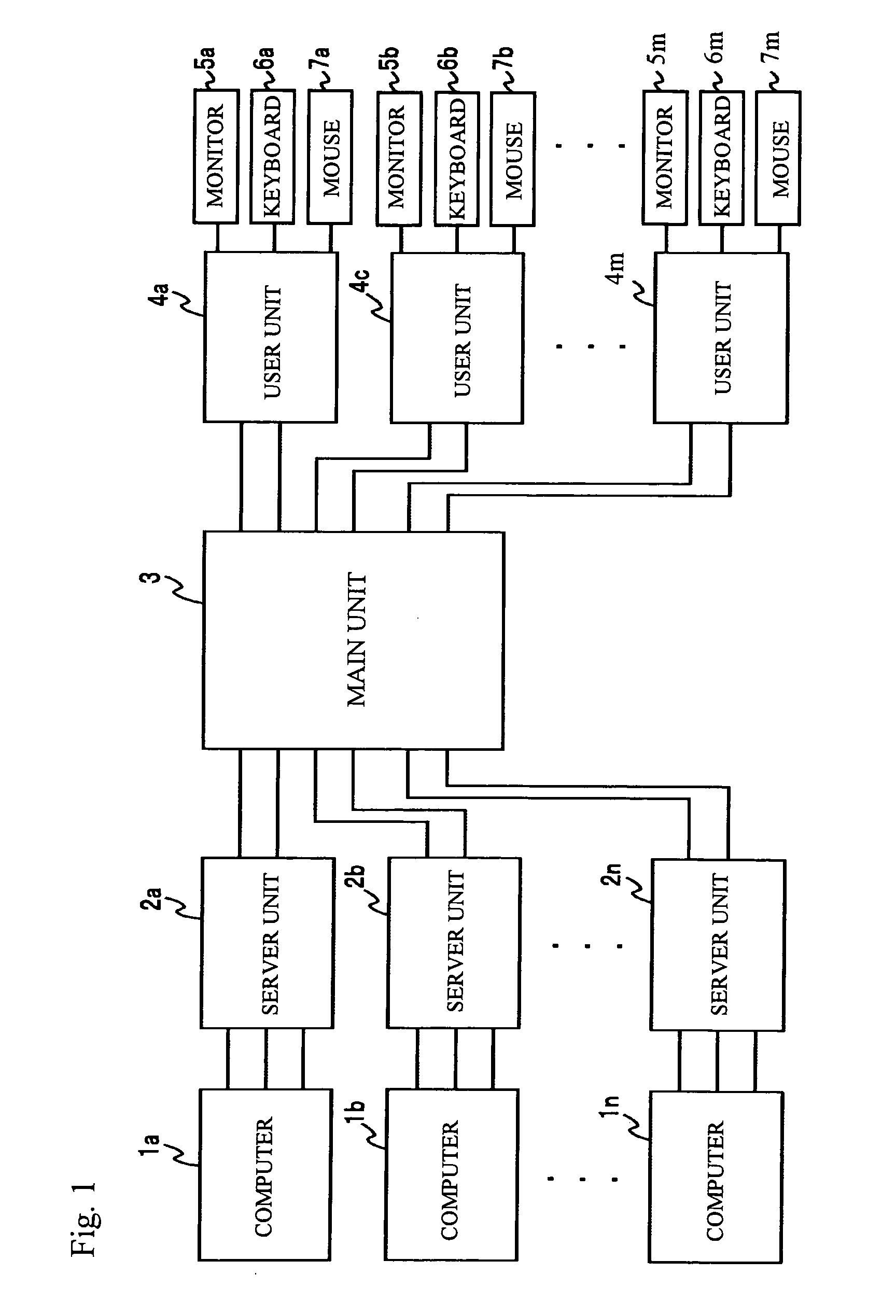
[0030]A KVM switch of a first embodiment has the same block configuration as shown in FIG. 1. That is, the KVM switch of the first embodiment includes the server units 2a through 2n to which the computers 1a through 1n are respectively connectable, the main unit 3, and the user units 4a through 4m to which input / output devices composed of monitors 5, keyboards 6 and mouses 7 are connectable.

[0031]FIG. 4 is a block diagram of a configuration of the server unit 2a employed in the first embodiment. Each of the other server units 2b through 2n is configured as shown in FIG. 4. The server unit 2a includes a video signal input section 31a, a video signal output section 32a, a signal processing section 33a, a microcomputer 34a and a memory 35a.

[0032]The video signal output by the computer 1a is applied to the video signal input section 31a of the server unit 2a, and is output to the video signal output section 32a. Then, the video signal from the video signal output section 32a is output ...

second embodiment

[0065]A second embodiment is directed to rewriting the version information and firmware when the version of the product is updated or a new model is available. An exemplary rewriting sequence is shown in FIG. 13.

[0066]A new firmware may be stored in a hard disc of the computer 1a, and the server unit 2a connected to the computer 1a acquires the new firmware.

[0067]As shown in FIG. 13, the server unit 2a is connected to the computer 1a by USB (Universal Serial Bus) or serial communication. Necessary information including firmware is acquired from the computer 1a via a communication line for firmware. When the firmware thus acquired is firmware of the server unit 2a, the server unit 2a rewrites the firmware stored in the memory 35a. When the acquired firmware is not firmware of the server unit 2a, the server unit 2a transfers the firmware to the main unit 3 by a firmware transfer command. The firmware and information transferred from the server unit 2a to the main unit 3 uses a signal ...


PUM


Abstract

A KVM switch includes: server units respectively connected to computers; user units respectively connected to input / output devices for transmitting signals to the computers and receiving signals from the computers; and a main unit that connects the server units and the user units. Each of the server units, user units and main unit is a communication unit and includes: a first part communicating with another communication unit to inform the above another communication unit of unit type information about the communication unit and receive unit type information about the above another communication unit therefrom; and a second part controlling communications with the above another communication unit on the basis of the unit type information acquired from the above another communication unit.

Description

BACKGROUND OF THE INVENTION[0001]1. Field of the Invention[0002]The present invention generally relates to a KVM switch used to selectively control computers by input / output devices each equipped with a keyboard, a mouse and a display.[0003]2. Description of the Related Art[0004]A KVM switch is provided between an input / output device and multiple computers, and makes a connection between the input / output device and any one of the computers. The user uses the KVM switch to select one of the computers that is to be connected to the input / output device.[0005]FIG. 1 shows a computer network including a KVM switch, which includes server units 2a, 2b, . . . , and 2n (n is a natural number), a main unit 3 and user units 4a, 4b, . . . , and 4m (m is a natural number). Computers 1a through 1n are connectable to the server units 2a through 2n, respectively. A monitor 5a, a keyboard 6a and a mouse 7a, which form an input / output device, are connectable to the user unit 4a. Similarly, a monitor ...

Claims


Application Information

Patent Timeline
IPC IPC(8): G06F3/033G06F3/02
CPCG06F3/023
Inventor SAKURAI, SATOSHIIDEURA, KATSUJIYASUNO, KAZUHIROSEKI, FUJIO
Owner FUJITSU COMPONENENT LTD
Why Eureka
Try Eureka