
Motorcycle Shock Light

a technology for shock lights and motorcycles, applied in cycle equipment, lighting and heating apparatus, light support devices, etc., to achieve the effect of easy removal and reattachmen

Inactive Publication Date: 2008-07-31
Q ENTERPRISE PRODN
View PDF9 Cites 8 Cited by
  • Summary
  • Abstract
  • Description
  • Claims
  • Application Information

AI Technical Summary

Benefits of technology

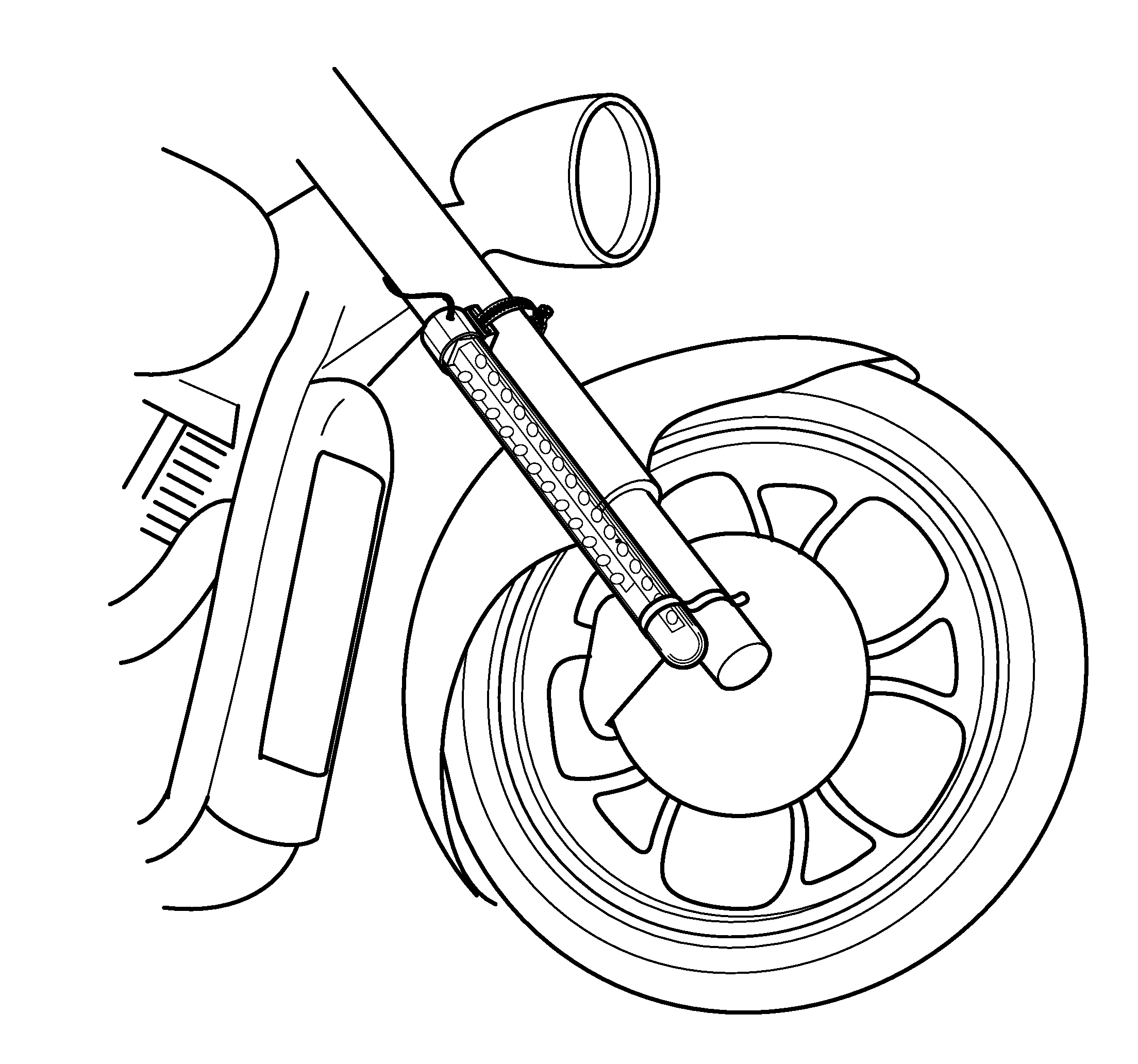
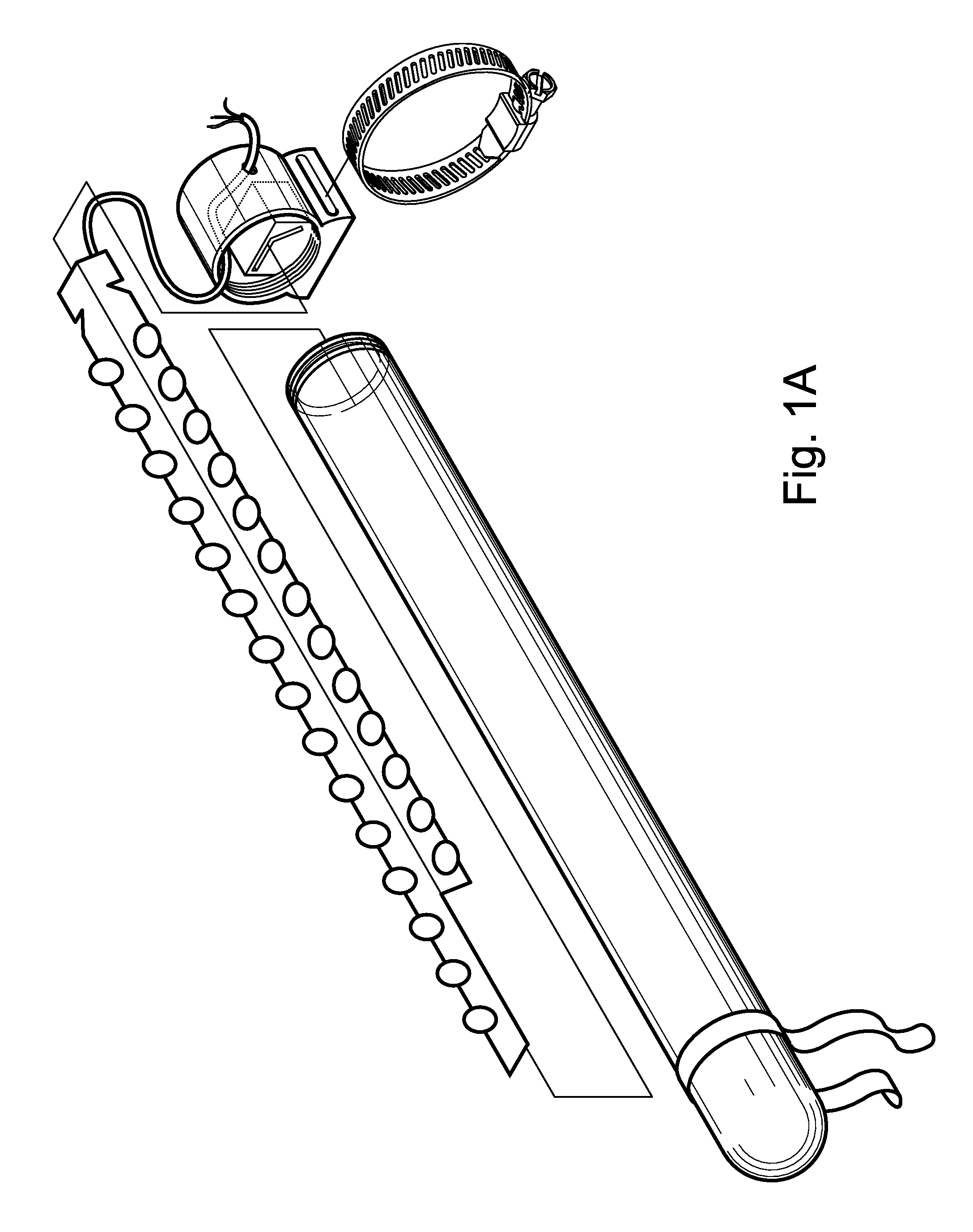
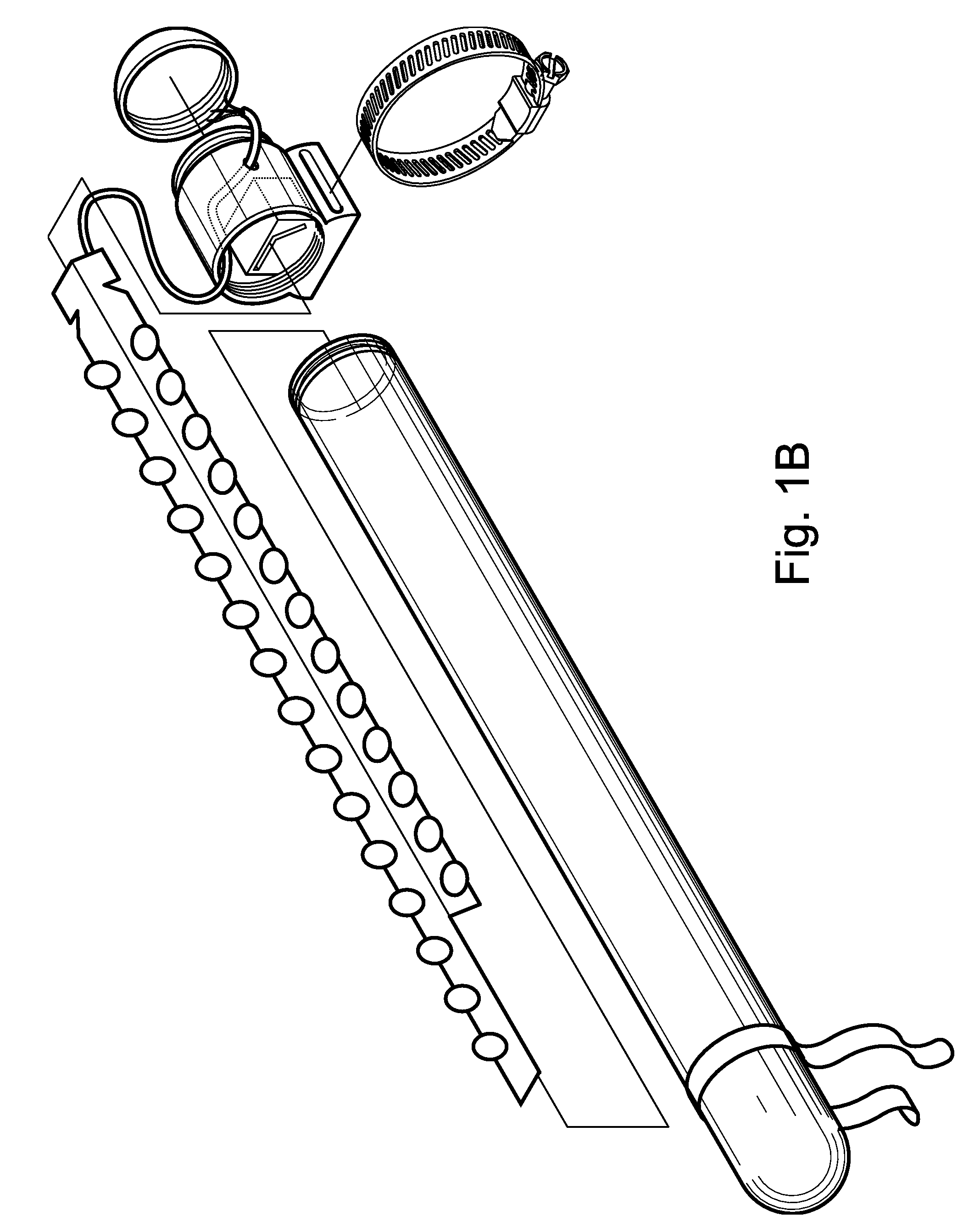
[0009]The tubular housing is translucent such that it allows light to shine through and may be easily removed and reattached by the motorcyclist. This tubular housing may be clear or one of many colors or multicolored. This translucent tubular housing thus allows the motorcyclist to change the appearance or color of the housing as desired for a particular application. The most typical choice may be clear, however various government agencies may use red or amber and police may want to use a blue colored tubular housing with differing on and off controls, for instance. Additionally, the LEDs may be different colors. Typically, the generally rear facing LEDs are red while the side facing LEDs are yellow or amber. With a clear tubular housing, these colors stand out while they become somewhat muted with colored housing.

Problems solved by technology

Second, another set of lights on the device is designed to shine in a generally rearward direction when the motorcycle is braking.

Method used


Image

  • Motorcycle Shock Light
  • Motorcycle Shock Light
  • Motorcycle Shock Light

Examples


Embodiment Construction

[0019]It is to be understood by a person having ordinary skill in the art that the present discussion is a description of exemplary embodiments only, and is not intended as limiting the broader aspects of the present invention. The following embodiment example is provided to further illustrate the invention and is not to be construed to unduly limit the scope of the invention.

[0020]The invention is an illumination device for motorcycles and similar personal transportation vehicles. The device comprises: jointed light strips, a cylindrical shaped tubular housing, and a base mount.

[0021]The base mount supports both the primary point of attachment to the motorcycle and the connections for the tubular housing and the light strip. The base mount also provides a shielded conduit through which the wiring of the light strips passes while traveling to the electrical power source of the motorcycle. The base mount is generally cylindrical in shape, except for the portion to be positioned adjac...


PUM


Abstract

The invention is a motorcycle shock mounted illumination device. The invention features a base mount with metal strap for primary attachment to a motorcycle shock, an angled pair of light strips created from circuit boards and LEDs and attached to the base mount, and a tubular housing that also attaches to the base mount. The tubular housing is translucent and encloses the light strips. The generally rearward facing light strip is designed to flash in red when the motorcycle brakes are applied and the generally sideward facing light strip is designed to be generally on all the time in yellow or amber except when the motorcycle brakes are applied in which case the LEDs of the side facing strip turn off and on in a grouped sequence.

Description

RELATED APPLICATIONS[0001]This application claims the benefit of the prior filed U.S. Provisional Application having Ser. No. 60 / 898,389.FEDERALLY SPONSORED RESEARCH OR DEVELOPMENT[0002]Not applicable.REFERENCED OR INCORPORATED MATERIAL[0003]Not applicable.SUMMARY OF THE INVENTION[0004]The invention is an illumination device for motorcycles and similar personal transportation vehicles. The illumination device is designed to provide illumination and opportunity for visual recognition to operators of other vehicles, especially at night and in conditions and areas of poor visibility. The illumination device attaches to the front shocks of the motorcycle. They thus form a set with one each, respectively, on the left side of the bike and on the right side of the bike.[0005]The device is designed to provide illumination for both safety purposes and aesthetic purposes. It also may be used as an indicator for special privileged emergency responder vehicles such as police motorcycles.[0006]T...

Claims


Application Information

Patent Timeline
IPC IPC(8): F21V33/00
CPCB60Q1/2661B60Q1/32B62K19/40B62J6/00B62J11/00B60Q1/44B62J6/01B62J6/045B62J6/26
Inventor EDMOND, MATTHEWEDMOND, RAQUEL L.
Owner Q ENTERPRISE PRODN
Learn More