Camera calibration device, camera calibration method, and vehicle having the calibration device

a calibration device and camera technology, applied in the field of image processing, can solve the problems of increasing the burden on the calibration operation as a whole, affecting the calibration environment, and reducing the accuracy of the calibration operation, so as to facilitate the maintenance of the calibration environment and reduce the effect of image degradation

Inactive Publication Date: 2008-07-31
SANYO ELECTRIC CO LTD
View PDF3 Cites 130 Cited by
  • Summary
  • Abstract
  • Description
  • Claims
  • Application Information

AI Technical Summary

Benefits of technology

[0014]One object of this invention, therefore, is to provide a camera calibration device and a camera calibration method that can reduce image degradation caused by errors with respect to kno...

Problems solved by technology

While the mounting angle of the camera and the installation height of the camera are often designed beforehand, errors may occur between such designed values and the actual values when a camera is installed on a vehicle, and therefore, it is often difficult to measure or estimate accurate transformation parameters.
The size of such a calibration pattern for example is twice that of the horizontal and vertical sizes of the vehicle, occupying a large space for the cal...

Method used


Image

  • Camera calibration device, camera calibration method, and vehicle having the calibration device
  • Camera calibration device, camera calibration method, and vehicle having the calibration device
  • Camera calibration device, camera calibration method, and vehicle having the calibration device

Examples


first embodiment

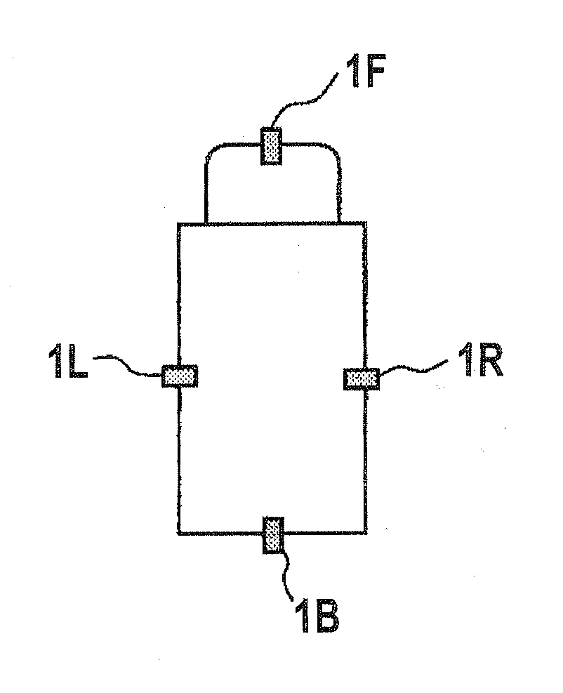
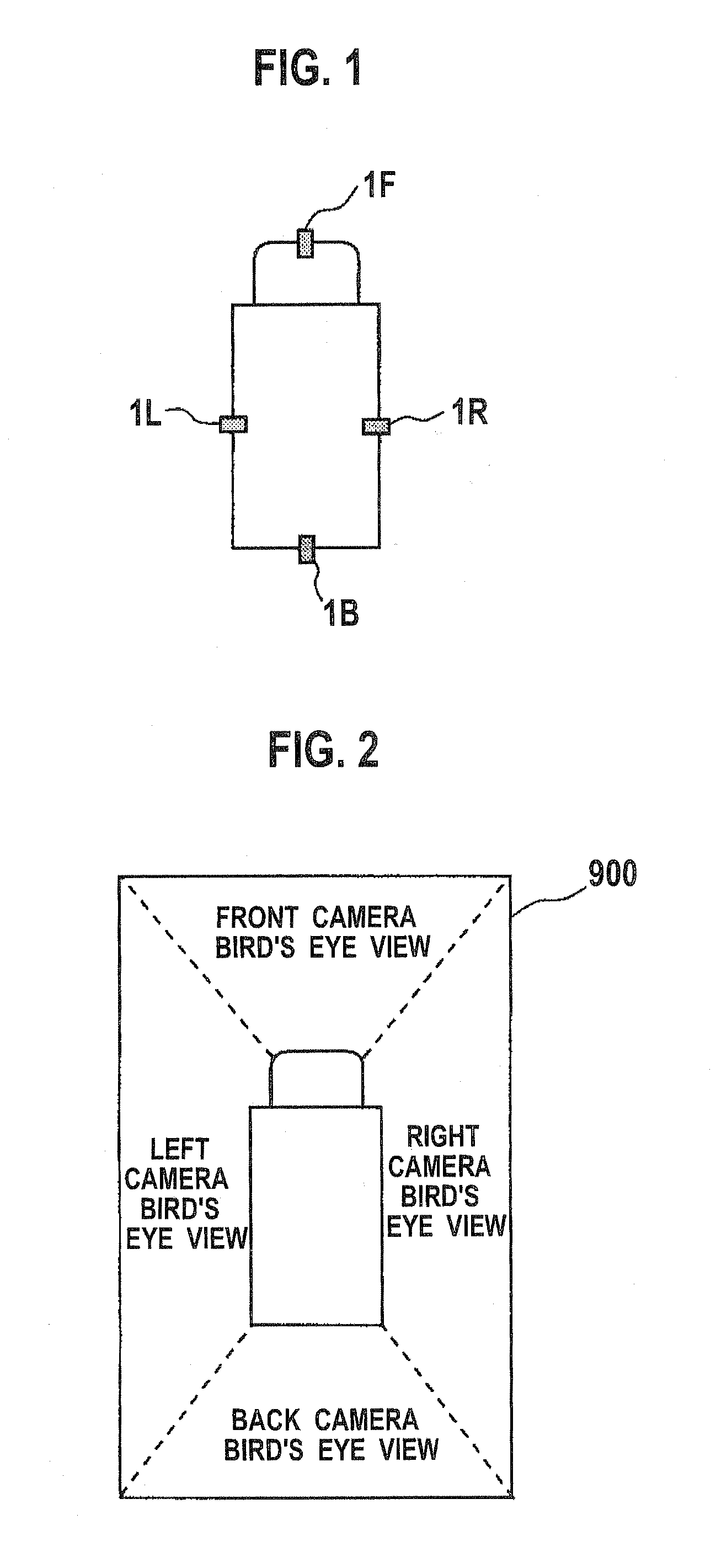
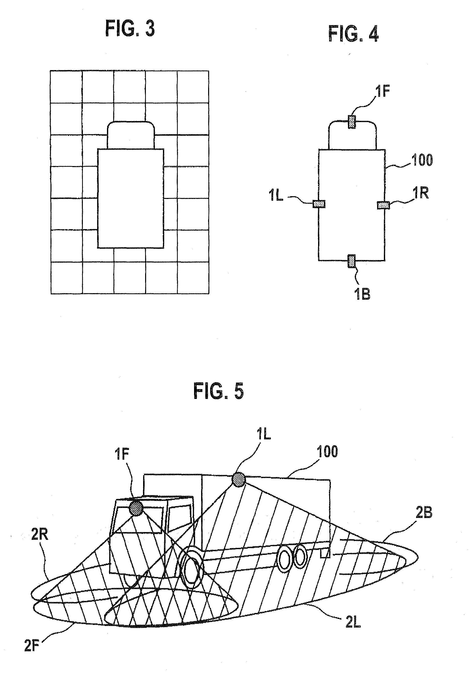
[0048]The first embodiment now will be explained. FIG. 4 is a plan view showing a vehicle 100 viewed from above in which a visibility support system of the first embodiment is applied, showing an arrangement of cameras on the vehicle 100. FIG. 5 is a perspective view of the vehicle 100 viewed obliquely from the front-left side. Although a truck is shown as the vehicle 100 in FIGS. 4 and 5, the vehicle 100 can be any other vehicle such as a regular passenger automobile. Also, the vehicle 100 is located on the ground such as a road surface. In the following explanations, the ground is assumed to be a horizontal plane and the “height” indicates a height with respect to the ground.

[0049]As shown in FIG. 4, cameras (image pickup devices) 1F, 1R, 1L, and 1B are mounted at the front part, the right side part, the left side part, and the back part of the vehicle 100 respectively. The cameras 1F, 1R, 1L, and 1B simply may be referred to as the cameras or each camera without being distinguish...

second embodiment

[0093]Moreover, by arranging the feature points as shown in FIG. 16, it is possible to perform the calibration processing as shown in FIG. 17. The embodiment of this processing will now be described as a second embodiment. The second embodiment corresponds to a variant of the first embodiment in which a part of the calibration processing method of the first embodiment is changed, and the content described in the first embodiment applies to the second embodiment as long as it is not contradictory. The calibration processing procedure that is different from the first embodiment will be explained below.

[0094]FIG. 17 is a flowchart showing a calibration processing procedure according to the second embodiment. First, at step S21, transformation parameters for the camera 1L as a reference camera is computed based on the perspective projection transformation. This computing method is the same as that of step S11 of FIG. 11.

[0095]Next, at step S22, four feature points (or more than four fea...

third embodiment

[0104]Next, the third embodiment will be explained. The third embodiment corresponds to a variant of the first embodiment in which a part of the calibration method of the first embodiment is changed, and the content described in the first embodiment applies to the third embodiment as long as it is not contradictory. The calibration processing procedure that is different from the first embodiment will be explained below.

[0105]In the third embodiment, a calibration pattern is used at the time of the calibration processing. FIG. 20 is a plan view of the periphery of the vehicle 100 showing an arrangement of each calibration pattern. As shown in FIG. 20, planar (two-dimensional) calibration patterns A1, A2, A3, and A4 are arranged within each of the common fields of view 3FR, 3FL, 3BR, and 3BL. The calibration patterns A1 to A4 are located on the ground.

[0106]Each of the calibration patterns has a square configuration having the length of each side e.g. about 1 m to 1.5 m. While it is n...


PUM


Abstract

Cameras are installed at the front, right, left, and back side of a vehicle, and two feature points are located at each of the common field of view areas between the front-right cameras, front-left cameras, back-right cameras, and back-left cameras. A camera calibration device includes a parameter extraction unit for extracting transformation parameters for projecting each camera's captured image on the ground and synthesizing them. After transformation parameters for the left and right cameras are obtained by a perspective projection transformation, transformation parameters for the front and back cameras are obtained by a planar projective transformation so as to accommodate transformation parameters for the front and back cameras with the transformation parameters for the left and right cameras.

Description

CROSS REFERENCE TO RELATED APPLICATIONS[0001]This application claims priority based on 35 USC 119 from prior Japanese Patent Application No. P2007-020495 filed on Jan. 31, 2007, the entire contents of which are incorporated herein by reference.BACKGROUND OF THE INVENTION[0002]1. Field of the Invention[0003]This invention relates generally to image processing, and more particularly to a camera calibration device and a camera calibration method which calibrates images from different cameras mounted at different positions with respect to each other, to combine the images and to project the combined image on a predetermined plane. This invention also relates to a vehicle utilizing such a calibration device and method.[0004]2. Description of Related Art[0005]With growing safety awareness of recent years, increased use has been made of a camera being mounted on a vehicle such as an automobile, or an on-vehicle camera, to provide an operation with increased visual awareness around the vehi...

Claims


Application Information

Patent Timeline
IPC IPC(8): G06K9/00
CPCB60R1/00B60R2300/102B60R2300/105B60R2300/303G06K9/00791B60R2300/607B60R2300/802B60R2300/8093B60R2300/402G06V20/56
Inventor ISHII, YOHEIKANO, HIROSHIASARI, KEISUKE
Owner SANYO ELECTRIC CO LTD
Why Eureka
Try Eureka