
Field of view matching in a visual prosthesis

Active Publication Date: 2008-07-31
CORTIGENT INC
View PDF10 Cites 29 Cited by
  • Summary
  • Abstract
  • Description
  • Claims
  • Application Information

AI Technical Summary

Problems solved by technology

While some of these early attempts met with some limited success, these early prosthetic devices were large, bulky and could not produce adequate simulated vision to truly aid the visually impaired.

Method used


Image

  • Field of view matching in a visual prosthesis
  • Field of view matching in a visual prosthesis
  • Field of view matching in a visual prosthesis

Examples


Embodiment Construction

[0039]The present disclosure is concerned with a visual apparatus and a method for creation of artificial vision. In particular, the present disclosure provides an interface and method for controlling a visual prosthesis (i.e. device) implanted in an individual patient (i.e. subject) to create artificial vision.

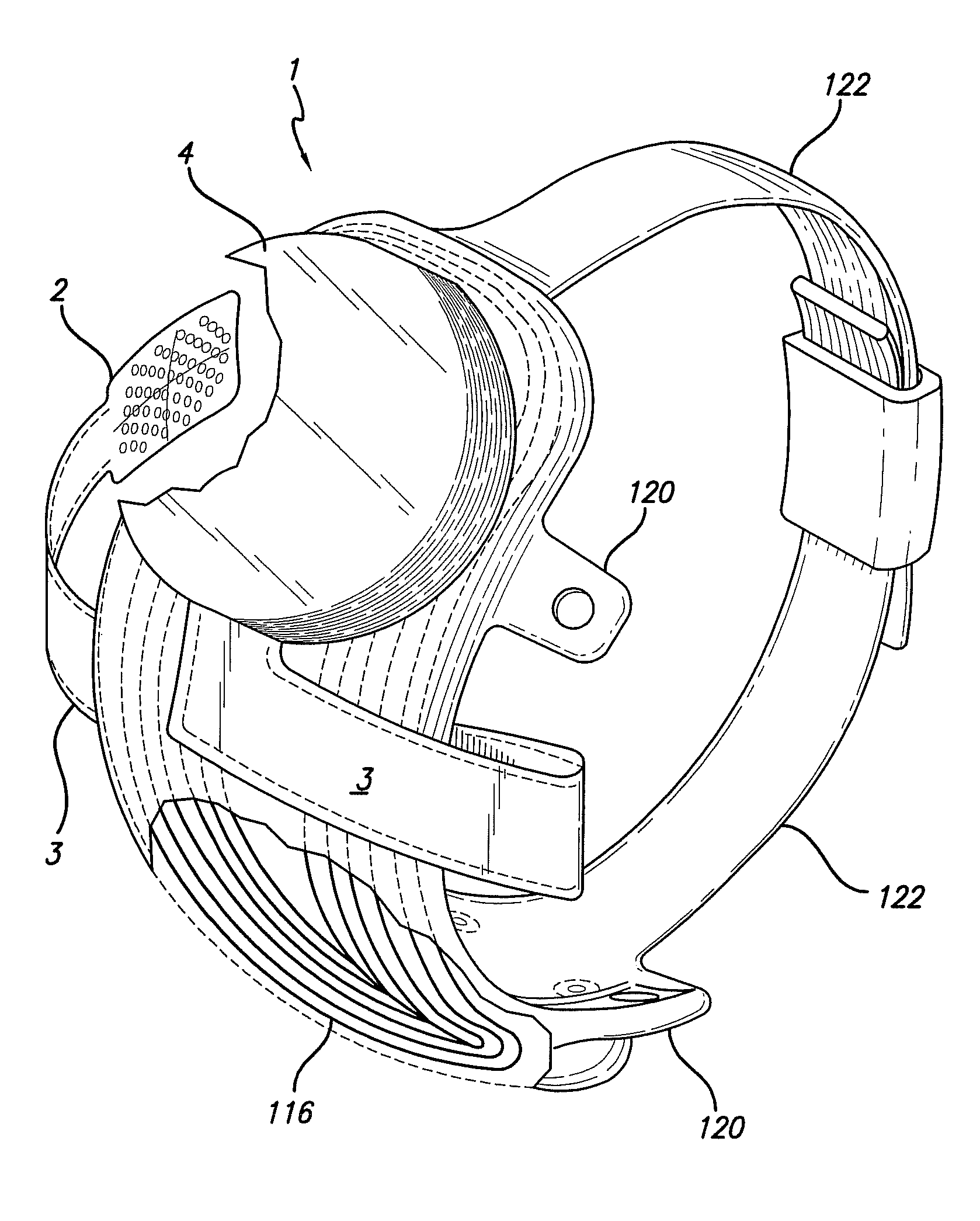
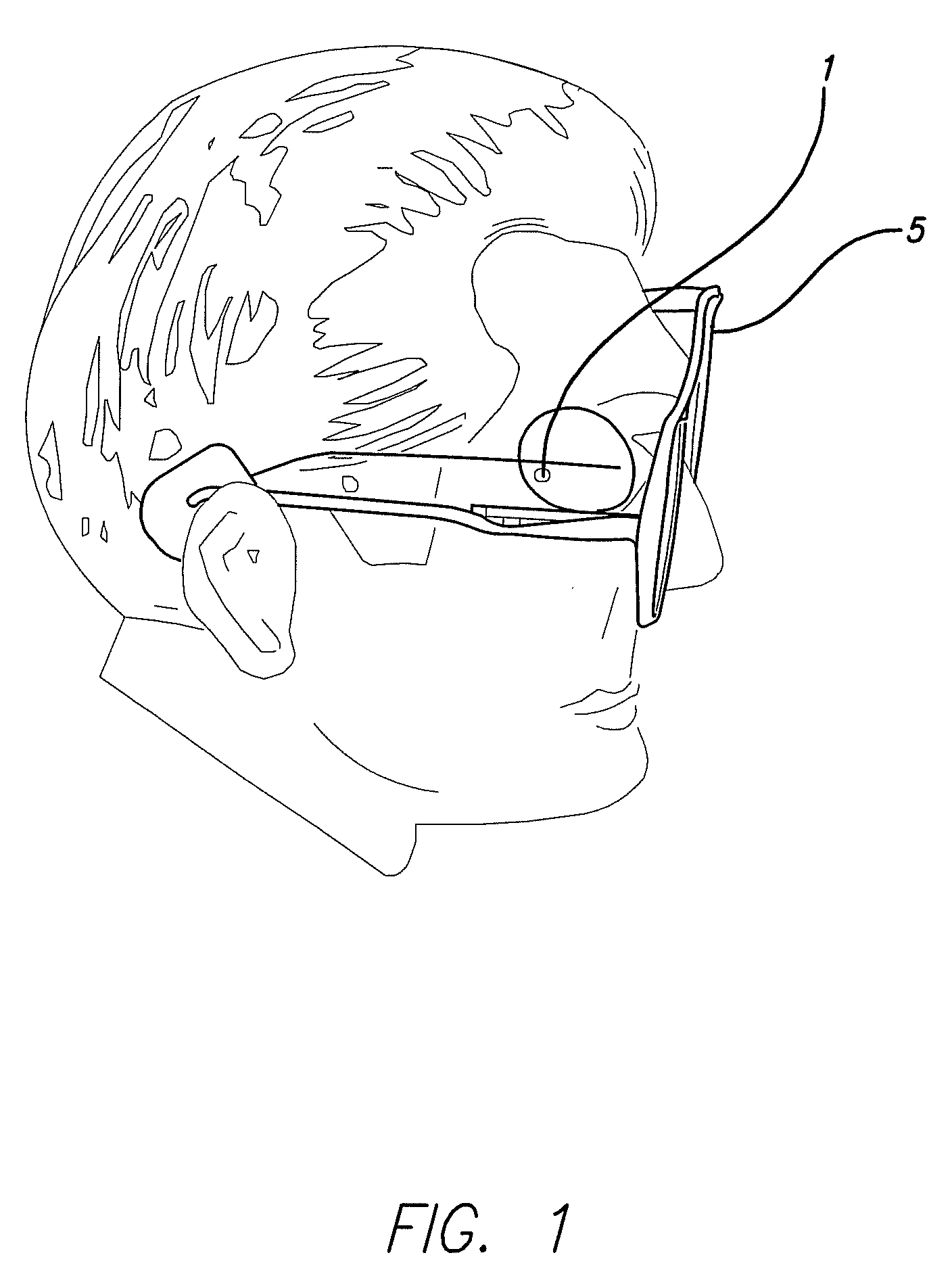
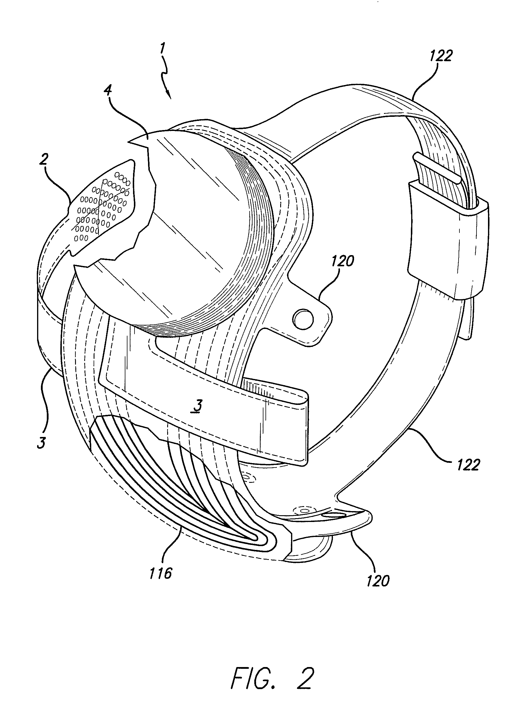
[0040]FIG. 1 shows a visual prosthesis apparatus. The visual apparatus comprises, in combination, an implantable retinal stimulation system 1 and a video capture / transmission apparatus or visor embodied in visor / Glasses 5. An exemplary retinal stimulation system 1 is shown in more detail in FIGS. 2-5 and an exemplary visor 5 is shown in more detail in FIGS. 6 and 7.

[0041]The retinal stimulation system 1 is further disclosed in U.S. application Ser. No. 11 / 207,644, filed Aug. 19, 2005 for “Flexible Circuit Electrode Array” by Robert J. Greenberg, et, al. incorporated herein by reference, and is intended for use in subjects with retinitis pigmentosa. The visor 5 is further disc...


PUM


Abstract

A visual prosthesis apparatus including a video capture device for capturing a video image, a video processing unit associated with the video capture device, the video processing unit configured to convert the video image to stimulation patterns, and a stimulation system configured to stimulate subject's neural tissue based on the stimulation patterns, wherein the stimulation system provides a span of visual angle matched to the subject's neural tissue being stimulated.

Description

CROSS REFERENCE TO RELATED APPLICATIONS[0001]This application claims the benefit of to U.S. Provisional Application Ser. No. 60 / 898,777 (Applicant's reference number S450-PRO), filed Jan. 31, 2007 for “Field of View Matching in a Visual Prosthesis”, the disclosure of which is incorporated herein by reference in its entirety.[0002]The present invention was made with support from the United States Government under Grant number R24EY12893-01, awarded by the National Institutes of Health. The United States Government has certain rights in the invention.FIELD[0003]The present invention is generally directed to neural stimulation and more specifically to an improved method of communication information to users and clinicians while fitting a visual prosthesis.BACKGROUND[0004]In 1755 LeRoy passed the discharge of a Leyden jar through the orbit of a man who was blind from cataract and the patient saw “flames passing rapidly downwards.” Ever since, there has been a fascination with electrical...

Claims


Application Information

Patent Timeline
IPC IPC(8): A61N1/05H04N7/18
CPCA61N1/0543A61B5/4836A61B3/1005A61N1/36046A61B5/0036
Inventor GREENBERG, ROBERT J.ROY, ARUPCASPI, AVRAHAM I.MCMAHON, MATTHEW J.
Owner CORTIGENT INC
Learn More