Image processing system, image processing device, job processing method, and recording medium
Active Publication Date: 2008-07-31
KONICA MINOLTA BUSINESS TECH INC
View PDF8 Cites 13 Cited by
Summary
Abstract
Description
Claims
Application Information
AI Technical Summary
This helps you quickly interpret patents by identifying the three key elements:
Problems solved by technology
Method used
Benefits of technology
Benefits of technology
[0011]The object of the present invention is therefore to provide an image processing system, an image processing device, a job processing method, and a recording medium that achieve smooth job processing and reduced cost in a structure including a plurality of image processing devices.
[0013]In the above-stated structure in which an unprocessed job is divided into a plurality of partial jobs, and each of a plurality of image processing devices judges, for each of the partial jobs, whether the own device can process a partial job, stores into the storage unit the first information indicating a condition with which the own device processes the partial job, obtains the second information indicating a condition with which another image processing device processes the partial job, and judges whether the own device should process the partial job, in accordance with a standard that is common to the plurality of image processing devices, by referring to the first information and the second information. The stated structure reduces the cost since the image processing system does not require a server as in conventional technologies. Also, this structure enables partial jobs to be processed by different image processing devices, enabling a job processing to be performed by a plurality of image processing devices in distribution, preventing processes from concentrating onto one device, thus realizing smooth job processing.
Problems solved by technology
In general, such a server is expensive, and imposes a burden of high cost to the user.
This may delay the start of the next job, and increase the job wait time.
Method used
Image
Click on the blue label to locate the original text in one second.
Reading with bidirectional positioning of images and text.
Examples
embodiment 1
[0050]Details, in structure, of the image processing device of the present embodiment and the image processing system including the image processing device will be provided in the following.
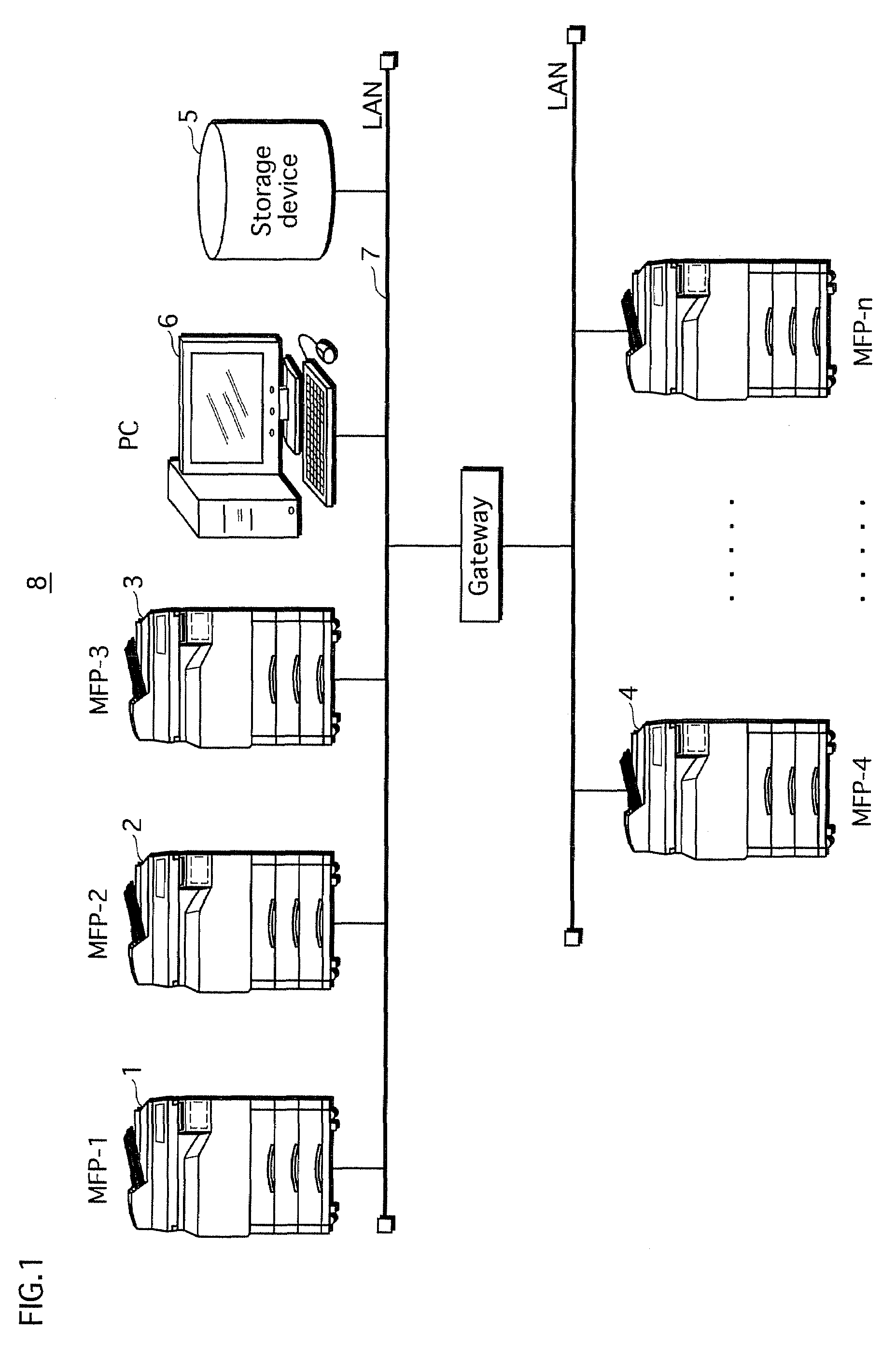
[0051]FIG. 1 schematically shows the overall structure of an image processing system 8.
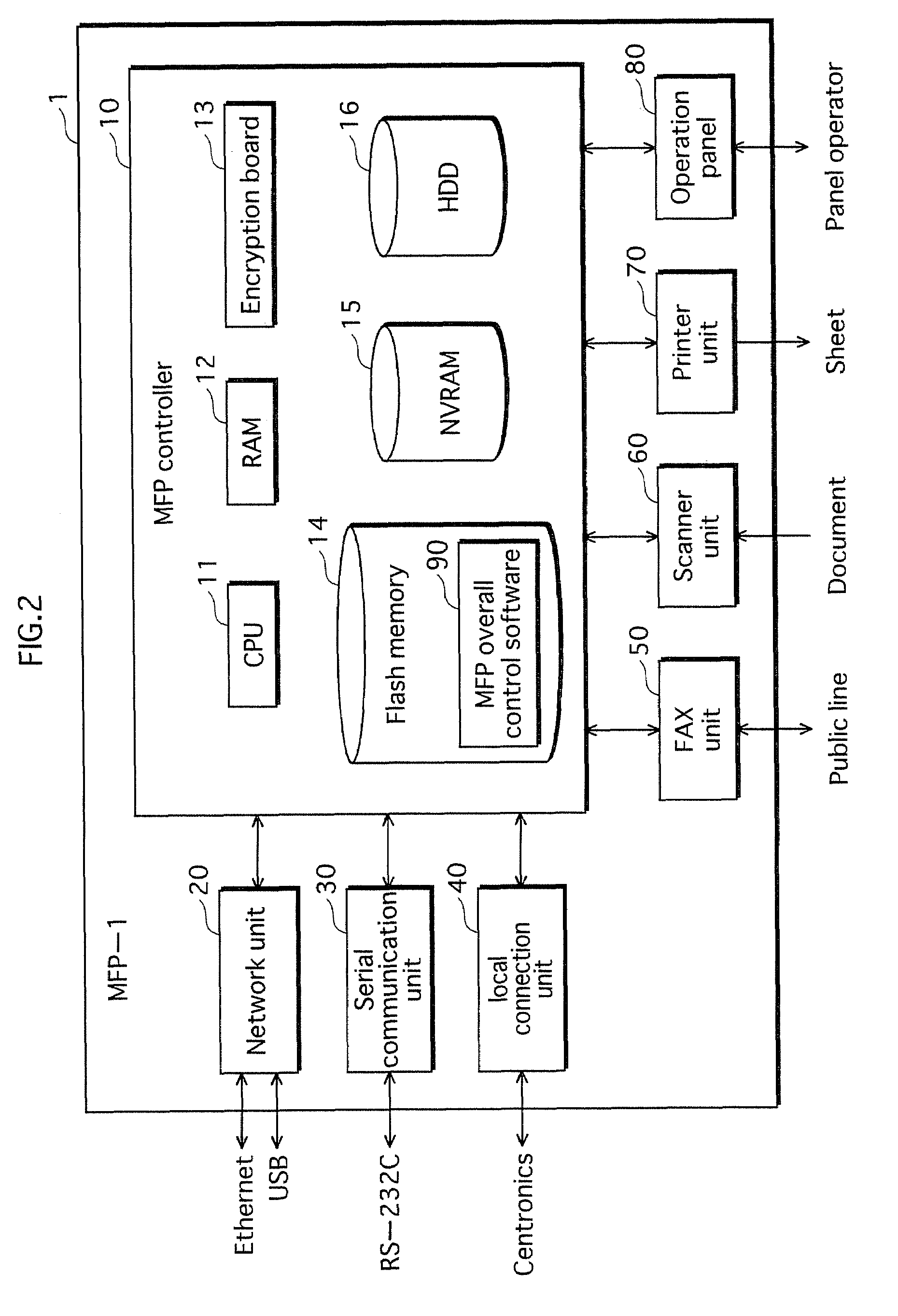
[0052]As shown in FIG. 1, the image processing system 8 includes MFPs (Multiple Function Peripherals) 1, 2, 3, 4, . . . n, a storage device 5, and a PC (Personal Computer) 5, which are connected with each other via a network 7 that is a LAN or the like. Each of the MFPs 1, 2, 3, 4, . . . n receives a request for processing a job, such as a scan, copy, print, or facsimile communication, from the user, and processes the job. The MFPs 1, 2, 3, 4, . . . n will be described in detail later.
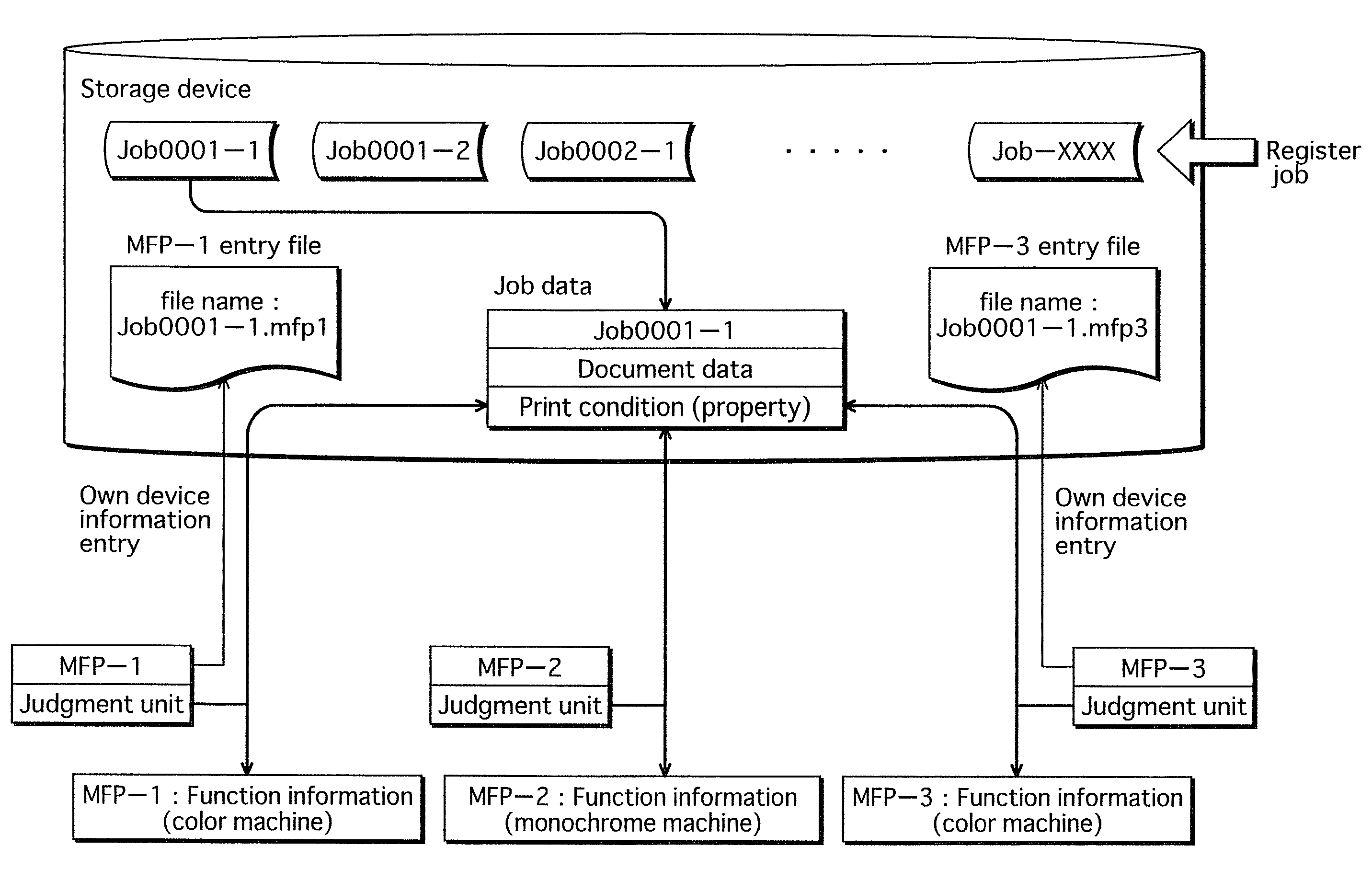
[0053]The storage device 5 is, for example, a NAS (Network Attached Storage) or HDD (Hard Disk Drive), and stores job data and entry files and the like, which will be described later.
[0054]The PC 6 is use...
embodiment 2
[0222]In Embodiment 1 described above, all the MFPs perform the job check at the same cycle. Embodiment 2 differs from Embodiment 1 in that the MFPs perform the job check not necessarily at the same cycle. In the following, to avoid redundancy, the description having already been provided in Embodiment 1 is omitted, and the same reference numbers are used for the constituent elements that are common with Embodiment 1.
[0223]FIG. 27 is a sequence diagram showing a detailed operation of the image processing system in Embodiment 2. It should be noted here that, in FIG. 27, the job judgment processing unit 96 and the access timermanagement unit 97 are respectively indicated in abbreviated forms “judgment unit” and “management unit”.
[0224]The access timer management units 97 of each of the MFPs 1, 2, and 3 generate an access timing signal at a predetermined cycle. The job judgment processing unit 96 of each of the MFPs 1, 2, and 3 confirms at a predetermined cycle whether there is an unp...
embodiment 3
[0234]The image processing system of Embodiment 3 differs from that of Embodiment 1 in that, if an image processing device judges in the second judgment that the own device is equal, neither advantageous nor disadvantageous, in comparison with the other devices, the image processing device adds a new piece of information for the judgment, and if the image processing device judges that the own device is advantageous in comparison with the other devices with respect to the newly added information, the image processing device processes the job.
[0235]FIGS. 28A and 28B show examples of entry files in the present embodiment. FIG. 28A shows entry files before information is newly added, and FIG. 28B shows entry files after information is newly added.
[0236]For example, if the entry files of the MFP 1 and MFP 3 are the same as shown in FIG. 28A, the job judgment processing units 96 of the MFP 1 and MFP 3 judge that the MFP 1 and MFP 3 are equal, and suspend the judgment on whether the own de...
PUM
Abstract
An image processingsystem including: storage; image processing devices; and job divider dividing an unprocessed job into partial jobs and store them into storage. Each image processing device includes: a first judging part to judge whether partial job stored in the storage can be processed by own device; a transmitter to, if the judgment result is positive, transmit and store first information indicating condition for processing the partial job, to the storage; an obtaining part to obtain second information indicating condition with which another image processing device processes the partial job, from the storage; a second judging part to judge whether own device should process the partial job, in accordance with standard common to the image processing devices, referring to first and second information; and job processor to process the partial job if second judging part judges positively.
Description
[0001]This application is based on application No. 2007-18429 filed in Japan, the contents of which are hereby incorporated by reference.BACKGROUND OF THE INVENTION[0002](1) Field of the Invention[0003]The present invention relates to an image processing system including a plurality of image processing devices, an image processing device, a job processing method, and a recording medium.[0004](2) Description of the Related Art[0005]Currently prevalent is image processing systems in which a plurality of client terminals, a plurality of image processing devices, and a job managementserver are connected with each other via a network such as a LAN, and each client terminal is able to cause each image processing device to execute a job via the job managementserver.[0006]In some of such image processing systems, when the job managementserver receives a request for processing a job from a client terminal, the job management server accesses a plurality of copiers in sequence to obtain (a)...
Claims
Application Information
Patent Timeline
Application Date:The date an application was filed.
Publication Date:The date a patent or application was officially published.
First Publication Date:The earliest publication date of a patent with the same application number.
Issue Date:Publication date of the patent grant document.
PCT Entry Date:The Entry date of PCT National Phase.
Estimated Expiry Date:The statutory expiry date of a patent right according to the Patent Law, and it is the longest term of protection that the patent right can achieve without the termination of the patent right due to other reasons(Term extension factor has been taken into account ).
Invalid Date:Actual expiry date is based on effective date or publication date of legal transaction data of invalid patent.

