Adjustable Height High Heel Shoe

a high heel shoe and adjustable technology, applied in the direction of shoes, top-pieces, heels, etc., can solve the problems of affecting the comfort of women's shoes, and occupying a lot of space in the bag, so as to prevent injury and facilitate use. the effect of the woman

Active Publication Date: 2008-08-07
FLANNERY SEAN
View PDF14 Cites 36 Cited by
  • Summary
  • Abstract
  • Description
  • Claims
  • Application Information

AI Technical Summary

Benefits of technology

[0011]It is another object of the present invention to provide a shoe with an adjustable heel that is easy and convenient for a woman to use.
[0012]It is further object of the present invention to provide a shoe with an adjustable heel that can be changed between the low and high heel states, quickly, without the need for tools and without the need to remove any of the shoe's parts.
[0013]It is a further object of the present invention to provide a shoe with an adjustable heel that is also aesthetically pleasing.
[0014]It is an even further object of the present invention to provide a shoe with an adjustable heel that is strong, secure and stable enough to prevent injury to the woman wearing the same.
[0015]In accordance with the illustrative embodiments demonstrating features and advantages of the present invention, there is provided a shoe having a sole with a toe portion, a heel portion and an arch portion located between them. A two part heel has a low heel block attached to the heel portion of the sole and includes a slot formed therein. A high heel extension piece is attached to the low heel block through a support beam having a substantially rectangular cross-section. The support beam is capable of limited axial and pivotal movement within slot. The dimensions of the support beam and the slot prevent rotational movement of the high heel extension piece about its central axis. The high heel extension piece can be pivoted relative to the sole between a first position wherein it underlies and is in alignment with the low heel block in a high heel configuration and a second position wherein it lies stowed beneath the arch portion of said sole and substantially parallel to the ground in a low heel configuration. The bottom of the low heel block has a low heel lift that extends downwardly and engages the ground when the high heel extension piece is stowed. This low heel lift is covered and completely hidden by a beveled edge at the top of the high heel extension piece when the heel mechanism is in its high heel configuration. A detent mechanism in the form of a spring biased ball incorporated within a rotatable pivot contained inside the low heel block and a depression in the support beam maintain the high heel extension piece in the desired position.

Problems solved by technology

This may pose a problem or, at the very least, an inconvenience as the woman would have to carry an extra pair of shoes to work and then change once she has arrived.
This creates a further problem if the woman finds that she needs a pair of shoes that have been left at the workplace, such as during the weekend.
This creates a problem when packing a suitcase in that many pairs of shoes need to be stored within a confined space.
Shoes are rather bulky and awkward to pack and often take up a lot of space within a bag.
Also, extended use of high heeled shoes may cause foot ailments.
The Schwartz solution is unacceptable as it requires a women to carry multiple heels with her and to attach the one that is desired each time she wishes to change the height of her heel.
This results in a rather complex arrangement.
It was subsequently found, however, that the mechanism that permitted such movement is not sufficiently stable or strong enough to prevent disengagement of the two heel parts with resultant collapse of the heel.
First, when in the high heel position, the wearer's weight is born almost entirely by the impaction of the high and low heel parts against each other and against the intervening low heel lift.
This spring / pin combination is inherently unstable because the pin, surrounded by a spring, can not be fitted within a channel with a tight enough tolerance to prevent wiggle and movement since an allowance must be made for the fact that the spring diameter changes between the states when it being compressed or distracted.
The result is that the mechanism is unstable and can easily allow the heel parts to wiggle and topple.

Method used


Image

  • Adjustable Height High Heel Shoe
  • Adjustable Height High Heel Shoe
  • Adjustable Height High Heel Shoe

Examples


Embodiment Construction

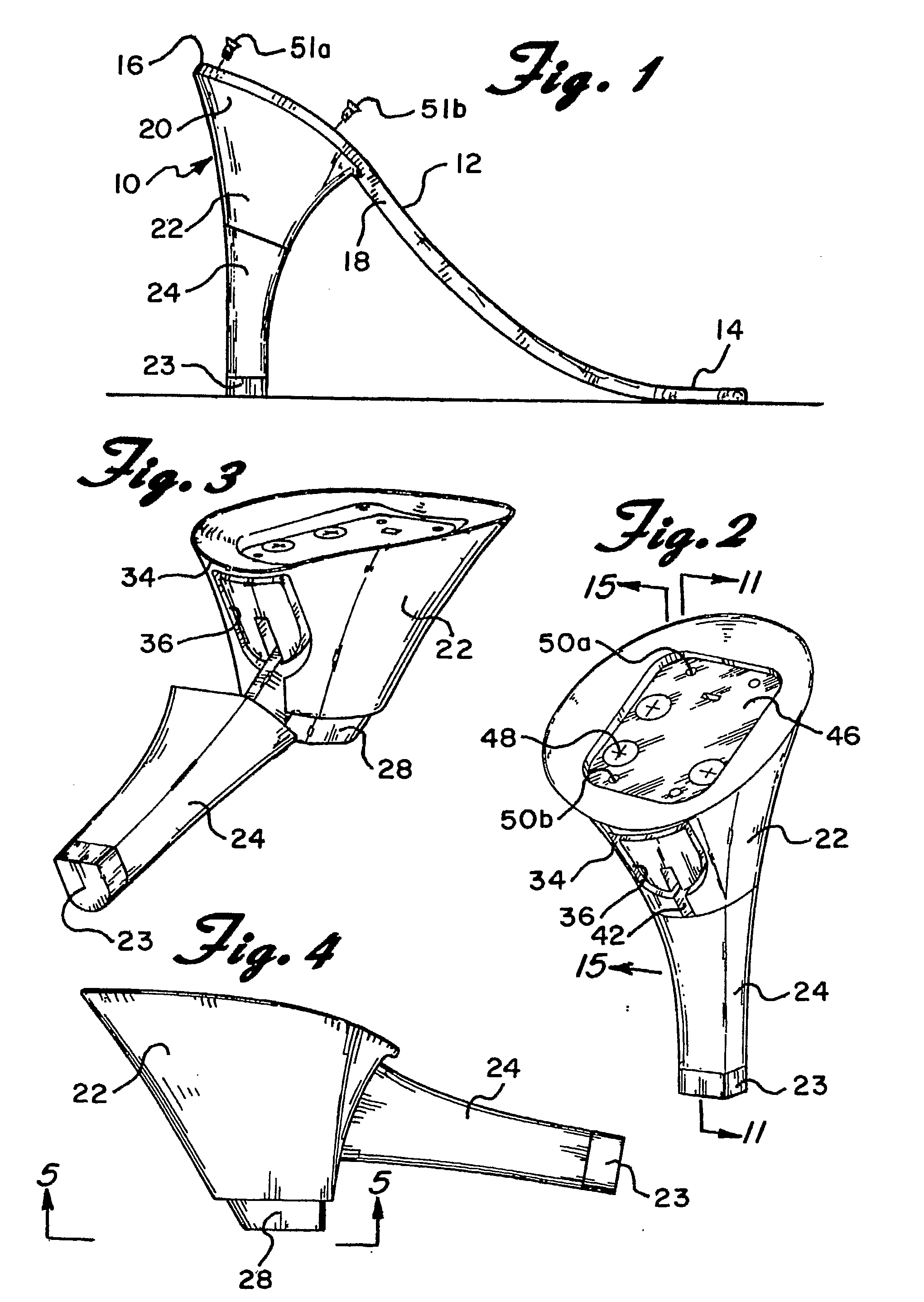
[0035]Referring now to the drawings in detail wherein like reference numerals have been used throughout the various figures to designate like elements, there is shown in FIG. 1 an adjustable high heel shoe constructed in accordance with the principles of the present invention and designated generally as 10.

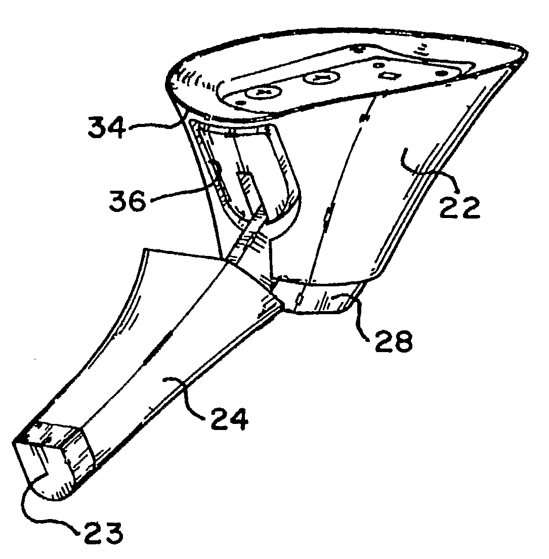
[0036]The adjustable shoe 10 of the present invention essentially includes a sole 12 with a toe portion 14, a heel portion 16 and an arch portion 18 located between the heel and toe portions. A stowable heel 20 is secured to the heel portion 16 of the sole 12. The heel may be secured to the sole by various methods known by those skilled in the arts including by screws as shown in the preferred embodiment. The sole 12 may take many forms as will be apparent to those skilled in the art. The essence of the present invention lies in the stowable heel 20.

[0037]The stowable heel 20 includes a low heel block 22 and a high heel extension piece 24 which is attached to the low heel block 22...


PUM


Abstract

A shoe (10) which has a sole (12) with a toe portion (14), a heel portion (16) and an arch portion (18) located between them. A two part heel (20) which has a low heel block (22) attached to the heel portion of the sole and includes a slot (42) formed therein. A high heel extension piece (24) is attached to the low heel block through a support beam (38) having a substantially rectangular cross-section. The support beam (38) is capable of limited axial and pivotal movement within slot. The dimensions of the support beam (38) and the slot (42) prevent rotational movement of the high heel extension piece (24) about its central axis. The high heel extension piece (24) can be pivoted relative to the sole (12) between a first position wherein it underlies and is in alignment with the low heel block (22) and a second position wherein it lies substantially beneath the arch portion (18) of said sole. The bottom of the low heel block has a low heel lift (28) that extends downwardly and engages the ground when the high heel extension piece (24) is stowed. This low heel lift (28) is completely enclosed and hidden by a beveled edge (32) at the top of the high heel extension piece (24) when it is in its vertical position high heel. A detent in the form of a spring biased ball (74) incorporated within a rotatable slotted pivot (52) and a depression (78) in the support beam (38) maintain the high heel extension piece (24) in the desired position.

Description

CROSS-REFERENCE TO RELATED APPLICATIONS[0001]This application claims the benefit of U.S. Provisional Patent Application Ser. No. 60 / 672,475, filed Apr. 18, 2005.TECHNICAL FIELD[0002]The present invention is directed toward an adjustable heel for high heel shoes and more particularly, toward a shoe heel that may be adjusted from a low heel to a high heel and vice versa.BACKGROUND ART[0003]Women often wear shoes with different heel heights. For example, when commuting, a woman may prefer to wear a low heeled shoes, flat shoes or sneakers. Wearing such shoes is more comfortable than wearing high heeled shoes when having to walk or drive a distance. Then, upon arriving at her place of business, she may prefer to wear a shoe with a higher heel. This may pose a problem or, at the very least, an inconvenience as the woman would have to carry an extra pair of shoes to work and then change once she has arrived. Alternatively, she may have to leave several pairs of shoes at the workplace. Thi...

Claims


Application Information

Patent Timeline
Patent Type & Authority Applications(United States)
IPC IPC(8): A43B3/24A43B21/36
CPCA43B3/24A43B21/433A43B21/42
Inventor HANDEL, DAVIDWHITE, IANWHITE, DAVID
Owner FLANNERY SEAN
Why Eureka
Try Eureka