Device and method for graphical mechanical ventilator setup and control

a technology of mechanical ventilator and graphical display, which is applied in the field of devices, can solve the problems of inability to provide clinicians with feedback, repeated steps, and difficulty in processes,

Active Publication Date: 2008-08-07
GENERAL ELECTRIC CO
View PDF8 Cites 59 Cited by
  • Summary
  • Abstract
  • Description
  • Claims
  • Application Information

AI Technical Summary

Benefits of technology

[0008]By the present invention, a user interface is provided for the control of a mechanical ventilator that promotes the design of custom respiratory therapy trajectories such as vent setup trajectories and vent procedure trajectories. The vent setup trajectory shapes the breath delivered by the ventilator. The vent procedure defines the sequence of multiple breaths or other events delivered by the ventilator. The user interface of the present invention allows the clinician to create the respiratory therapy trajectory and visually observe the trajectory in graphical form as the clinician creates the trajectory. Alternatively, the clinician can select from a variety of standard or model vent setup or vent procedure trajectories, and modify these trajectories to specifically tailor the respiratory therapy to the needs of the patient. As the clinician modifies a parameter of the trajectory to be delivered to the patient, the interface of the present invention displays back to the clinician a numerical setting that is dependent upon the modifications made by the clinician such that the clinician is made aware of the effects of the modification of a particular ventilator setting.

Problems solved by technology

There are several limitations, however, associated with current ventilatory systems and the means by which the respiratory therapy trajectories may be modified for the clinician to provide the proper respiratory therapy to the patient.
This tedious sequence of steps must be repeated to change additional parameters.
These processes are difficult for the clinician because it requires pre-computation of many of the ventilatory parameters as well as the management of these ventilatory parameters.
Additionally, current ventilatory systems do not provide the clinician with feedback comprising the resulting effects that the modification of the ventilatory parameters by the clinician has on other parameters of the ventilatory system.
This may confuse a clinician who must switch between various ventilator platforms.
These differences make it difficult for clinicians to operate and / or become proficient at the use of multiple brands of ventilators.

Method used


Image

  • Device and method for graphical mechanical ventilator setup and control
  • Device and method for graphical mechanical ventilator setup and control
  • Device and method for graphical mechanical ventilator setup and control

Examples


Embodiment Construction

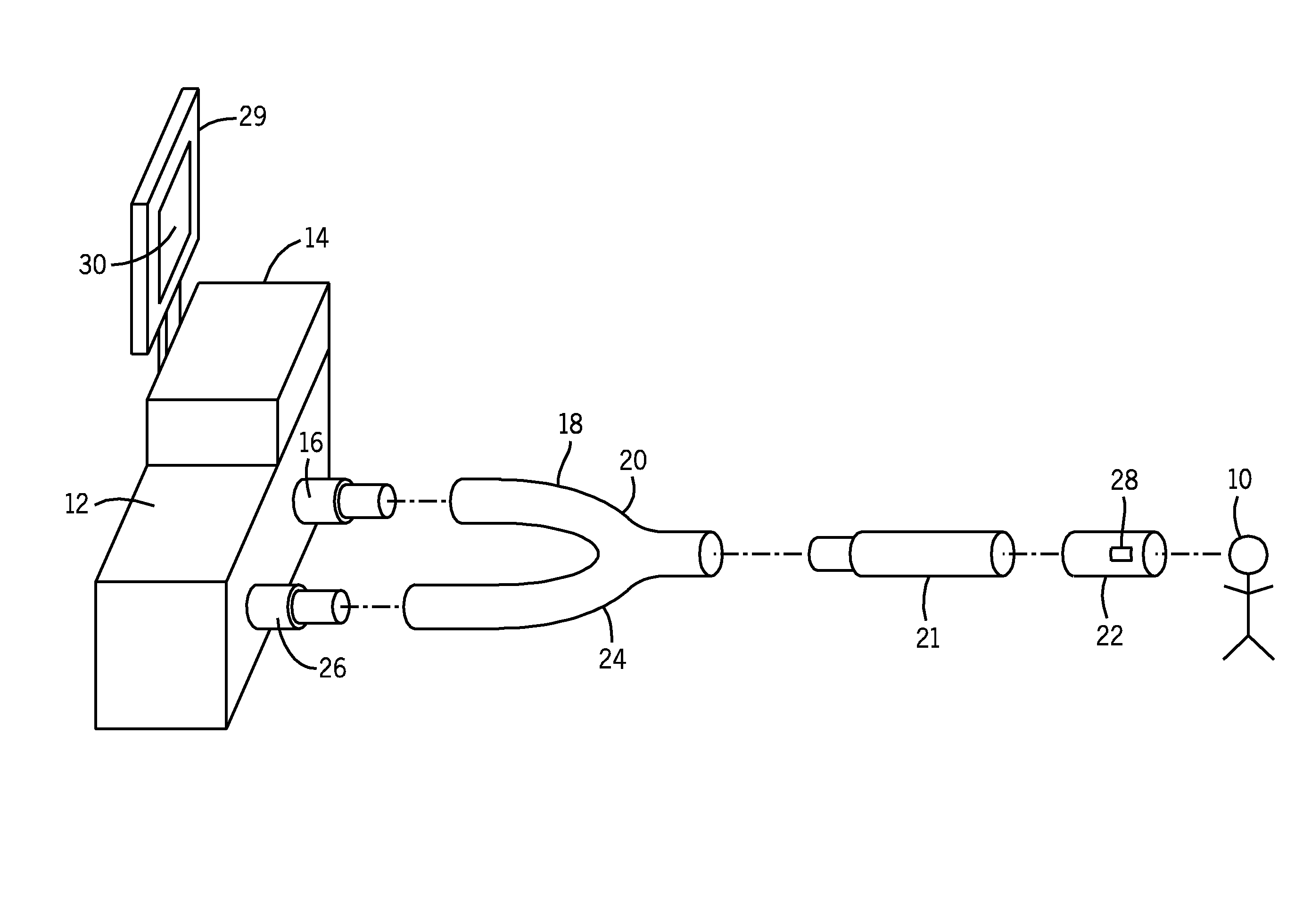
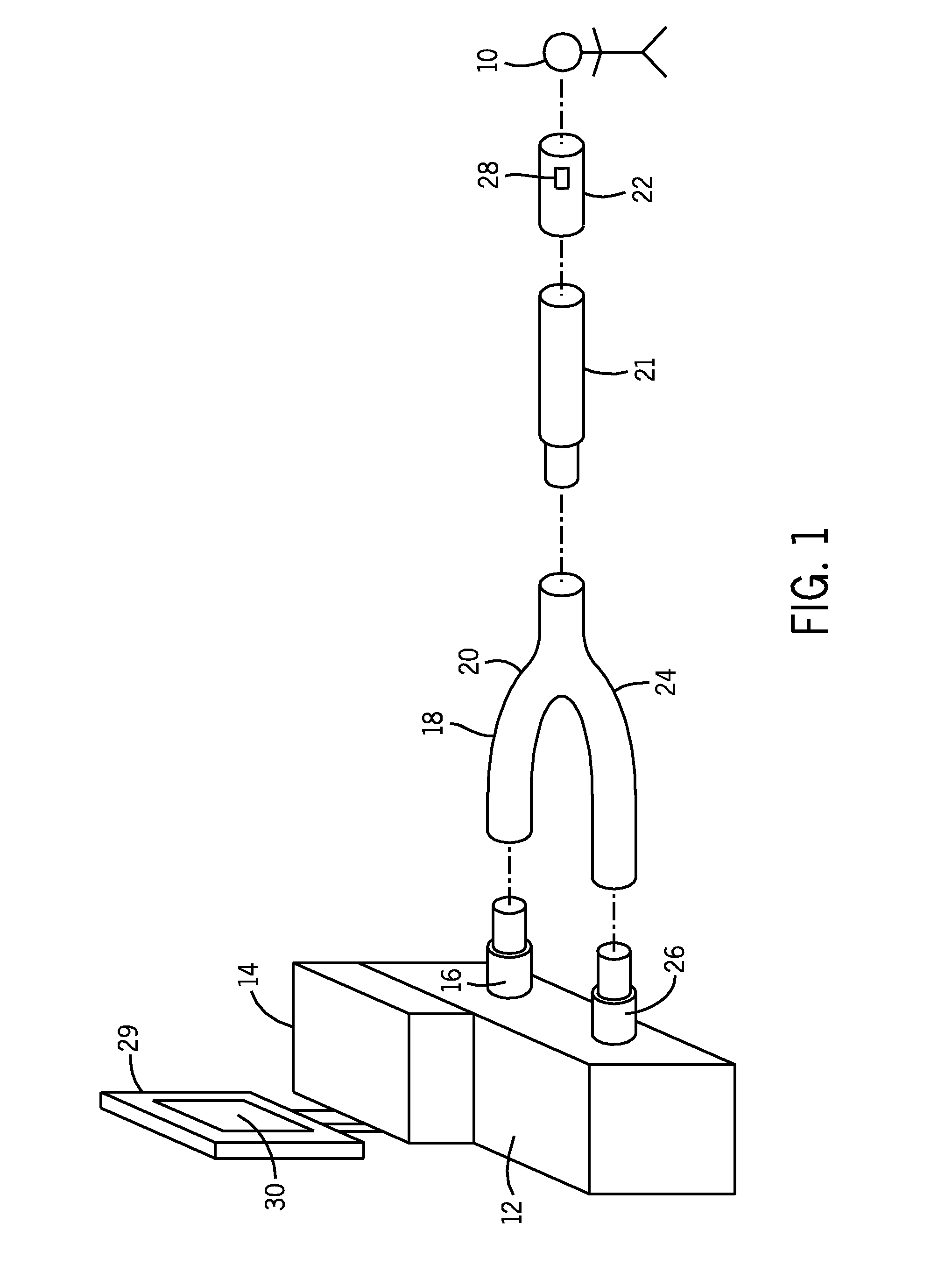
[0028]FIG. 1 depicts a ventilatory system comprising the user input device 29 of the present invention. A patient 10 receives respiratory therapy from a mechanical ventilator 12 through a series of connected pneumatic tubes. Typically, the ventilator 12 comprises a controller 14 that operates the ventilator 12 to deliver the proper respiratory therapy to the patient 10. This respiratory therapy is delivered to the patient according to a respiratory therapy trajectory. A clinician then monitors the waveform of medical gas produced within the ventilator system by the controller 14 following the trajectory. Typically, the controller 14 will be a CPU; however, it is understood that other forms of microcontrollers and / or microprocessors may be used in accordance with this invention.

[0029]In delivering a breath of medical gas to the patient 10, the ventilator 12 sends a flow of medical gas through an inspiratory port 16 where it enters the inspiratory limb 18 of a breathing circuit 20. Th...


PUM


Abstract

An input device for a clinician to control and modify the operation of a mechanical ventilator comprises a graphical display, a representation of a respiratory therapy trajectory to be delivered to a patient, at least one data point associated with the trajectory, and a data input means for the clinician to select a data point and to modify the value of the trajectory at that data point. The present invention provides for the creation and modification of a respiratory therapy trajectory, wherein the ventilator provides a medical gas waveform to a patient according to the respiratory therapy trajectory.

Description

FIELD OF THE INVENTION[0001]The present invention relates to the field of mechanically assisted patient ventilation. More specifically, the present invention relates to a new method and device for a clinician to use in modifying specific aspects of the respiratory therapy that is to be provided by the mechanical ventilator to the patient. By the present invention, a clinician is able to intuitively interact with the mechanical ventilator to create a new respiratory therapy, thereby increasing the efficiency of the selection and implementation of the desired respiratory therapy.BACKGROUND OF THE INVENTION[0002]Mechanical ventilation is a commonly accepted medical practice for the treatment of individuals experiencing respiratory problems. These patients may not be spontaneously breathing at all, such as a patient that may be in an intensive care unit. In these instances, mechanical ventilation is provided according to a clinician defined respiratory therapy trajectory. Alternatively,...

Claims


Application Information

Patent Timeline
Patent Type & Authority Applications(United States)
IPC IPC(8): A61B19/00
CPCA61B2017/00199A61M16/00A61M16/024A61M2205/502A61M2205/505
Inventor CHONCHOLAS, GARY J.MICHELI, PAUL R.ACKER, JARON M.THAM, ROBERT Q.
Owner GENERAL ELECTRIC CO
Why Eureka
Try Eureka