

Blowout Preventer Testing System And Method
- Summary
- Abstract
- Description
- Claims
- Application Information
AI Technical Summary
Benefits of technology
Problems solved by technology
Method used
Image

Examples
Embodiment Construction
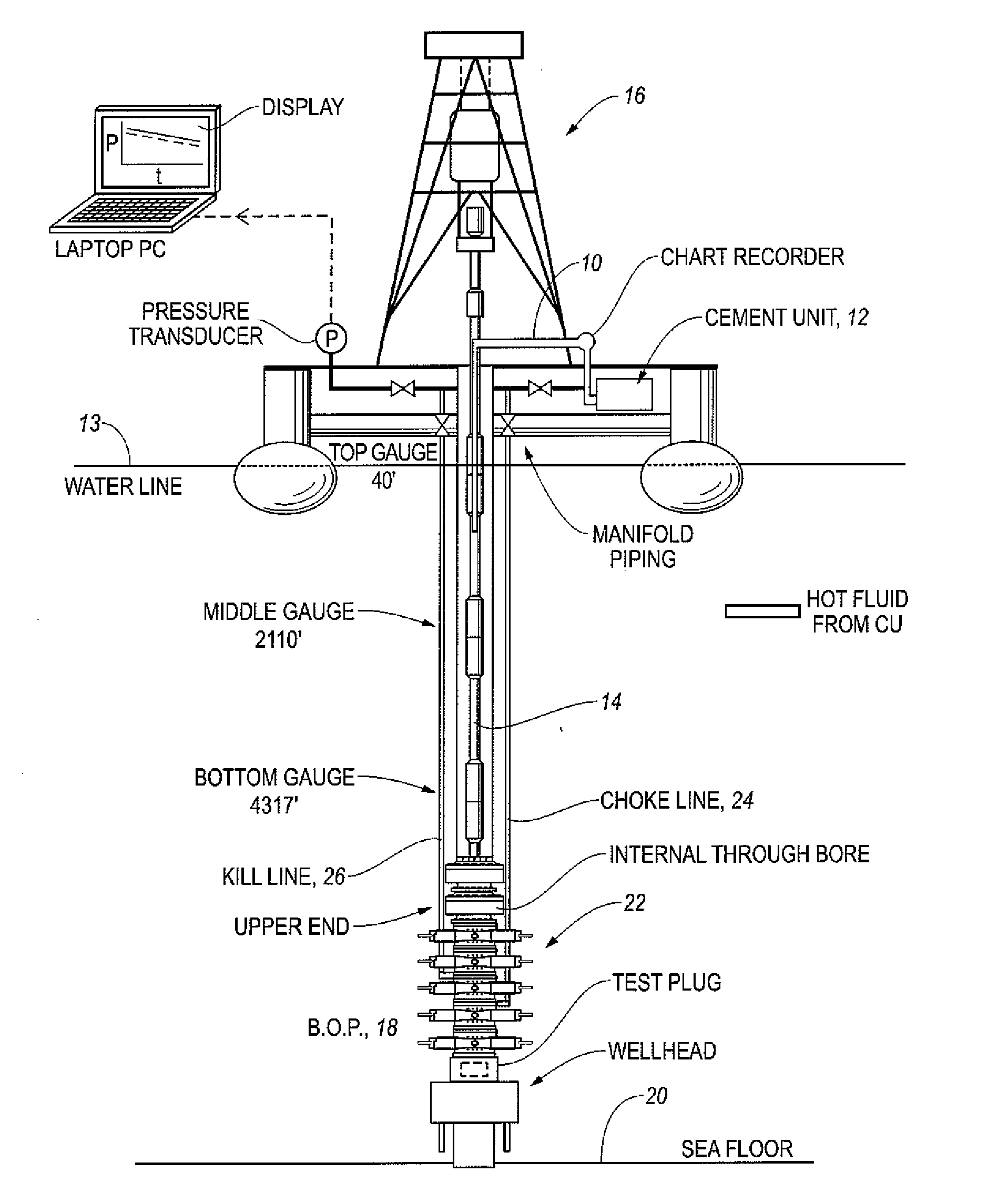
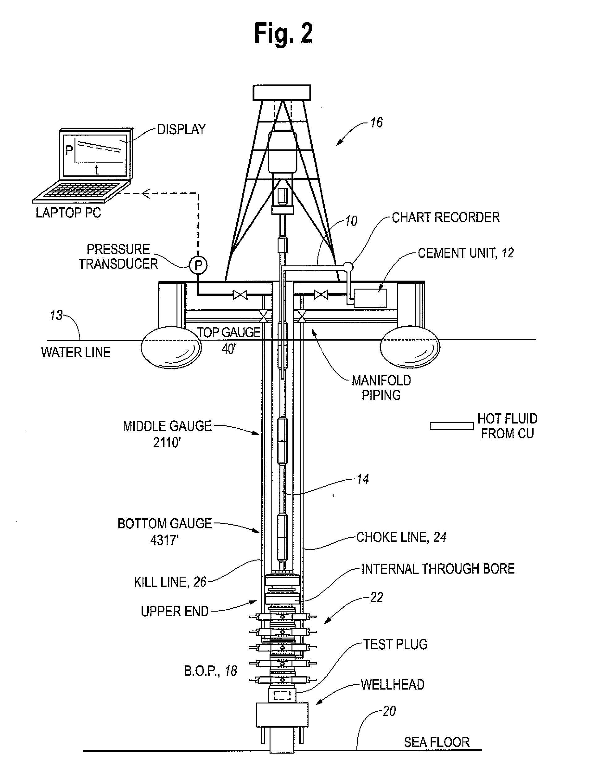
[0042]While this invention is a susceptible embodiment in many different forms, there is shown in the drawings, and will herein be described in detail, one specific embodiment of the invention. It should be understood, however, that the present disclosure is to be considered an exemplification of the principles of the invention and is not intended to limit the invention to any specific embodiment so described.
Digital BOP Testing Algorithm
[0043]To enable real time interpretation of subsea blowout preventer tests, a digital BOP testing algorithm was developed. Many specific approaches may be taken; preferably, the algorithm should obtain accurate pressure forecasts and have good predictive capability. The algorithm is used to fit observed or actual pressure data, and a pressure trend is extrapolated. Finally, a test criteria is applied to check for confidence in the pressure forecast.
[0044]Pump rate, volume pumped and pump pressure data are received in approximately 1-second intervals...
PUM
 Abstract
Description
Claims
Application Information