Eureka AIR delivers breakthrough ideas for toughest innovation challenges, trusted by R&D personnel around the world.

Yoke assembly for stator of starter motor

Inactive Publication Date: 2008-08-07
DENSO CORP
View PDF2 Cites 18 Cited by
  • Summary
  • Abstract
  • Description
  • Claims
  • Application Information

AI Technical Summary

Benefits of technology

[0010]With the yoke assembly for the starter motor of the present embodiment, the auxiliary pole and the magnet spring are unitized as the subassembly, making it possible to assemble the auxiliary pole and the magnet spring in the same process in which a magnet spring of a stator motor in the absence of an auxiliary pole is assembled. Thus, the assembling processes can be performed in common arrangement, resulting in improved mass production effect and reduction in manufacturing cost.
[0012]With such a structure, the auxiliary pole and the magnet spring can be assembled to each other by simply causing the concaved portion and the convexed portion to be brought into mating engagement with each other. This enables the subassembly to be assembled to the yoke at low cost.
[0014]The structure, in which the auxiliary pole has the protrusion formed by embossing and the magnet spring has the mating hole formed by punching, results in the work being performed with ease and a resultant excellent productivity. In this case, it is mostly practical to take a structure with two protrusions each formed in a circular shape and two mating holes each formed in a round shape, resulting in an excellent productivity and durability.
[0017]In a preferable structure, the magnet spring has two rectangular fixture holes formed at longitudinally spaced positions and the bulging portions are formed on the inner peripheral wall of the yoke at longitudinally spaced positions in correspondence to the locations of such fixture holes so as to protrude radially inward to the center of the yoke. The bulging portions protrude from the back plate of the magnet spring under the mating states so as to extend toward the center of the yoke. Subsequently, protruded areas are caulked and expanded, thereby causing the magnet spring to be fixedly secured to the inner peripheral wall of the yoke. When caulking, almost no part of the protrusion of the auxiliary pole protrudes to the inward area of the magnet spring. This allows the use of the same caulking tool as that used for caulking the bulging portions of the yoke for the structure in the absence of the auxiliary poles, making it possible to perform caulking processes in common arrangement. This results in an advisable effect of achieving remarkably improved productivity at low manufacturing cost.
[0019]With the subassembly formed in such a structure, almost no part of the convexed portion of the auxiliary pole protrudes into the inside area of the magnet spring, thereby ensuring the magnet spring to have the same internal airspace as that achieved in a structure in the absence of the auxiliary poles.
[0020]Therefore, the yoke assembly of the present embodiment can have the same structure as that of a stator in which pole-to-pole magnets are assembled to a yoke in the absence of auxiliary poles. This enables the pole-to-pole magnets to be additionally incorporated into the inside (mounting chamber) of the magnet spring. Such a structure enables the yoke assembly to be smoothly assembled in a structure including both the auxiliary poles and the pole-to-pole magnets with a consequence of less leakage of magnetic fluxes between the main poles. This enables the starter of the starter motor with improved output performance to be realized at low cost.

Problems solved by technology

Therefore, this results in a need to take an assembling process that is different from a yoke assembling for a structure employing only main poles in the absence of the auxiliary poles.
As a result, when manufacturing starter motors of two types such as a starter motor on which the stator elements having the auxiliary poles are mounted and a starter motor on which only the main poles are mounted, plural assembling processes are needed, resulting in a difficulty of achieving a reduction in manufacturing cost on mass production.

Method used


Image

  • Yoke assembly for stator of starter motor
  • Yoke assembly for stator of starter motor
  • Yoke assembly for stator of starter motor

Examples


first embodiment

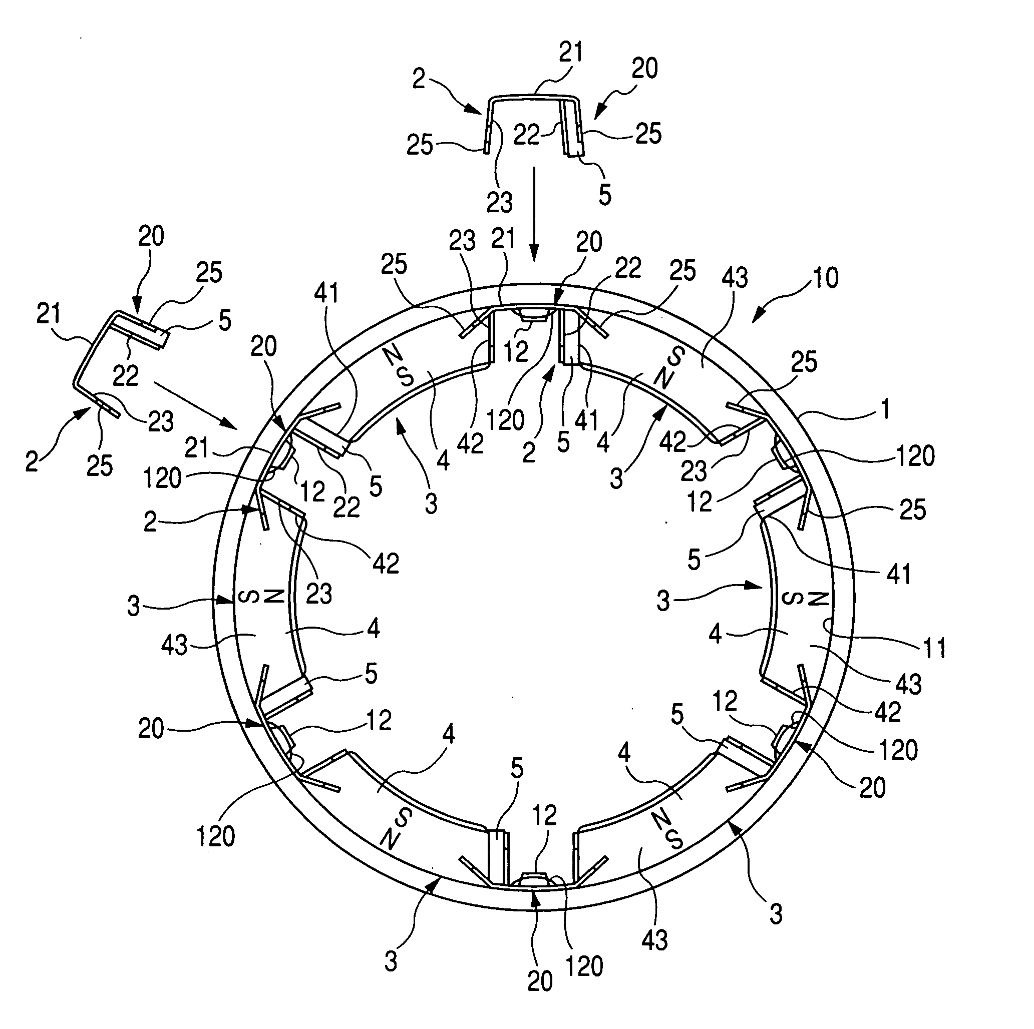
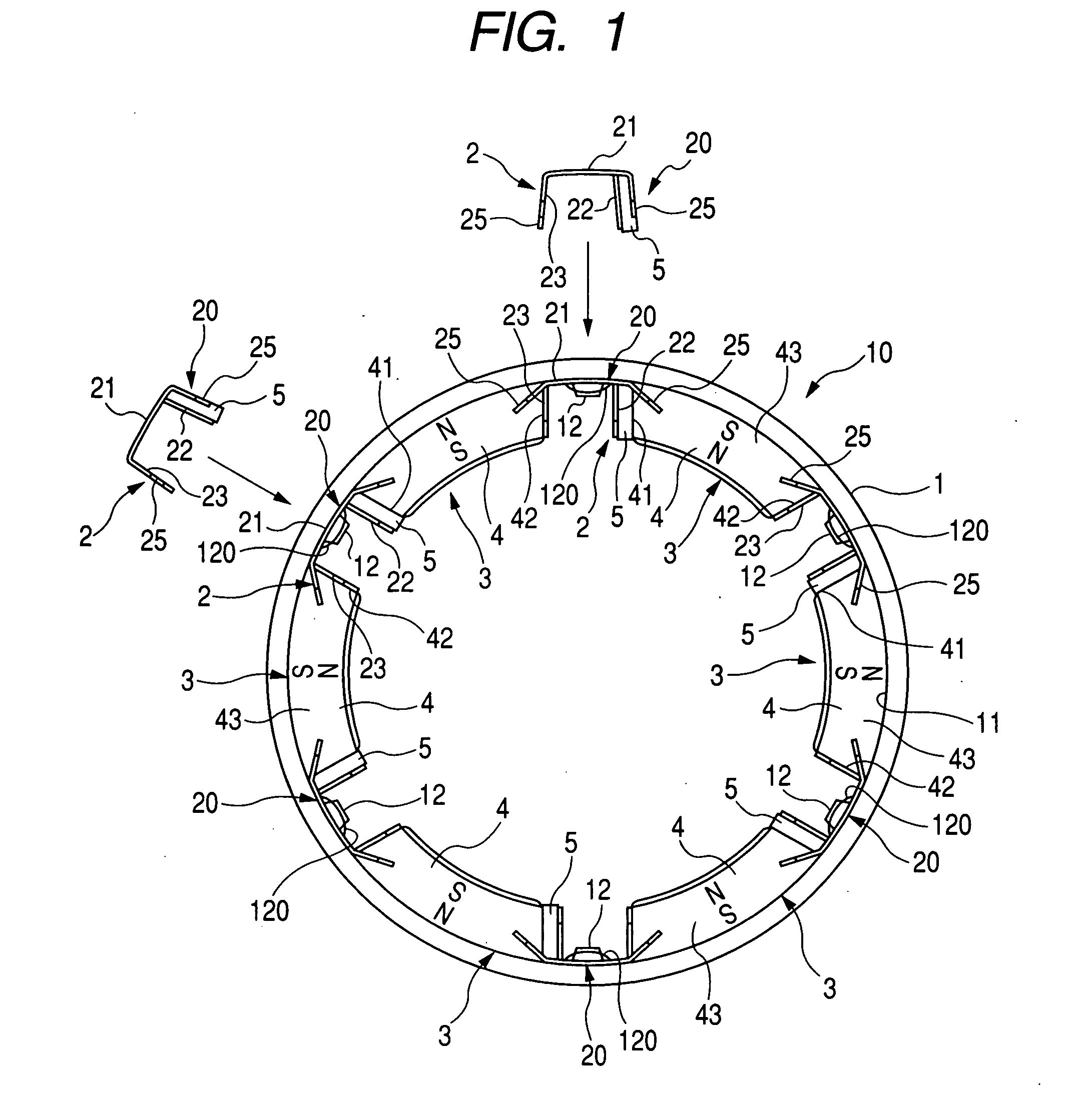
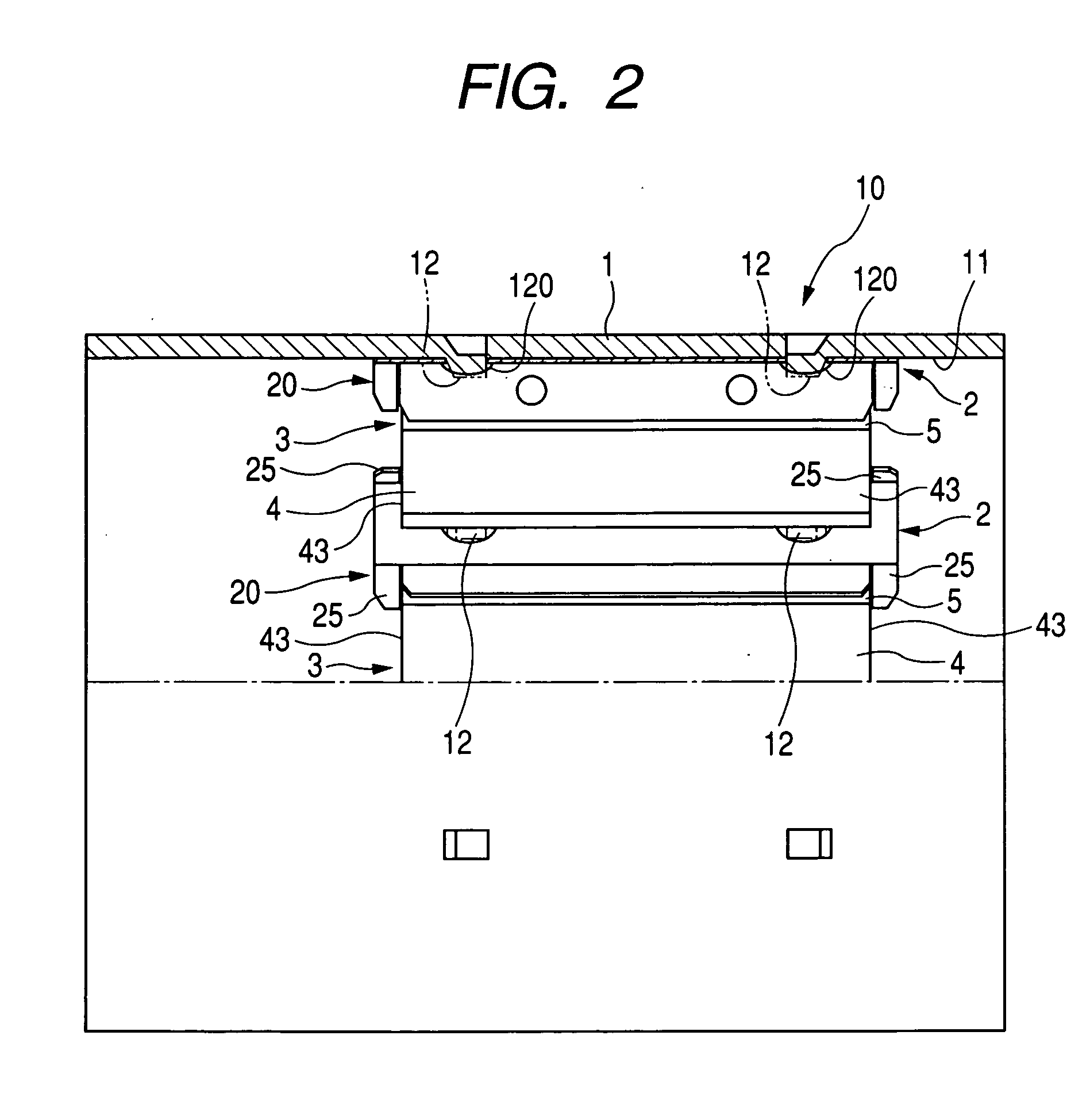
[0038]A yoke assembly of one embodiment according to the present invention for use in a stator of a starter motor mounted on an automotive engine is described below with reference to FIGS. 1 and 2.

[0039]As shown in FIGS. 1 and 2, the yoke assembly 10 includes a cylindrical yoke 1 having an inner circumferential periphery 11, a plurality of magnet springs 2 fixedly secured to the inner circumferential periphery 11 of the cylindrical yoke 7 at equidistantly spaced intervals along a circumferential direction of the inner circumferential periphery 11, and a plurality of stator elements 3 retained with the magnet springs 2, respectively. A fundamental structure of the starter motor to which the yoke assembly 10 is applied is well known in the art and an armature, having a rotary shaft (not shown), is coaxially accommodated in the yoke 1.

[0040]With the present embodiment, the inner peripheral wall 11 of the yoke 1 carries thereon six magnet springs 2, fixedly secured at circumferentially ...

second embodiment

[0048]A yoke assembly of a second embodiment according to the present invention will be described below in detail with reference to FIGS. 6 to 8.

[0049]FIG. 6 shows the yoke assembly 10A of the present embodiment. With the present embodiment, the yoke assembly 10A takes the form of a structure including stator elements 3A each of which includes a main pole 4 and an auxiliary pole 5, placed in direct contact with a magnet spring 2A and each of which has a pole-to-pole magnet 6 placed inside the magnet spring 2A.

[0050]As shown in FIGS. 7 to 7C, each magnet spring 2 has an interior, formed in a mounting chamber 60 for the pole-to-pole magnet 6, and has both side plates 22 and 23. The side plates 22 and 23 have radially inward areas, closer to the center of the yoke assembly 10A, which are formed with ledge segments 2a and 2a circumferentially extending inward from the side plates 22 and 23. The ledge segments 2a and 2a serve as holder sections for holding each pole-to-pole magnet 6 to c...


PUM


Abstract

A yoke assembly for a stator of a starter motor is disclosed including auxiliary poles and magnet springs, with each of auxiliary poles and each of the magnet springs taking the form of a subassembly. The subassembly, composed of each of the auxiliary poles preliminarily mounted on each of the magnet springs, is fixedly secured to an inner peripheral wall of a yoke. This allows the subassemblies to be easily assembled to the yoke in the same process as that in which a yoke assembly is assembled using the magnet springs in the absence of the auxiliary poles, providing assembling processes in common with an increase in mass production effect.

Description

CROSS REFERENCE TO RELATED APPLICATIONS[0001]This application is related to Japanese Patent Application No. 2007-22361, filed on Jan. 31, 2007, the content of which is hereby incorporated by reference.BACKGROUND OF THE INVENTION[0002]1. Technical Field of the Invention[0003]The present invention relates to stators for starter motors mainly for use in starting up automotive engines and, more particularly, to a yoke assembly for a stator of a starter motor having a cylindrical yoke whose inner peripheral wall carries thereon magnet springs each of which supports a stator element composed of a permanent magnet, serving as a main pole, and an auxiliary pole placed adjacent to the permanent magnet on an increasing magnetic flux side thereof.[0004]2. Description of the Related Art[0005]Attempts have heretofore been made to use a D.C. motor as a magnetic-field type starter employing a permanent magnet. With such a motor, a stator includes a cylindrical yoke having an inner peripheral wall ...

Claims


Application Information

Patent Timeline
IPC IPC(8): H02K1/18H02K1/17
CPCH02K1/17
Inventor HIRABAYASHI, TAKASHI
Owner DENSO CORP
Why Eureka
Eureka Blog
Learn More