
Methods and systems of a multiple radio frequency network node RFID tag

Inactive Publication Date: 2008-08-07
TEGO INC
View PDF15 Cites 92 Cited by
  • Summary
  • Abstract
  • Description
  • Claims
  • Application Information

AI Technical Summary

Benefits of technology

[0010]Coordination may include accessing combined memory. Coordination facilitates redundancy among RF network nodes. Coordination facilitates data encryption. Coordination may be according to a network topology among the RF network nodes. The network topology may be a ring network topology. a mesh network topology, a serial topology, a packet-based network topology, or the like.
[0215]The card may be a debit card. Items may be automatically purchased with the debit card using a reader. The debit card may provide automatic identification of a user.
[0216]The card may be a smart card. Items may be automatically purchased with the smart card using a reader. The smart card may provide automatic identification of a user.
[0217]The card may be an ATM card. Items may be automatically purchased with the ATM card using a reader. The ATM card may provide automatic identification of a user.

Problems solved by technology

However, current RFID tags suffer from performance problems.
Passive tags, while not requiring a local power source, suffer from low bandwidth and high failure rates in data transmission.
Active tags, while performing better than passive tags, are much more expensive and require a power source.
The vehicle may be denied access if the vehicle failed inspection.

Method used


Image

  • Methods and systems of a multiple radio frequency network node RFID tag
  • Methods and systems of a multiple radio frequency network node RFID tag
  • Methods and systems of a multiple radio frequency network node RFID tag

Examples


Embodiment Construction

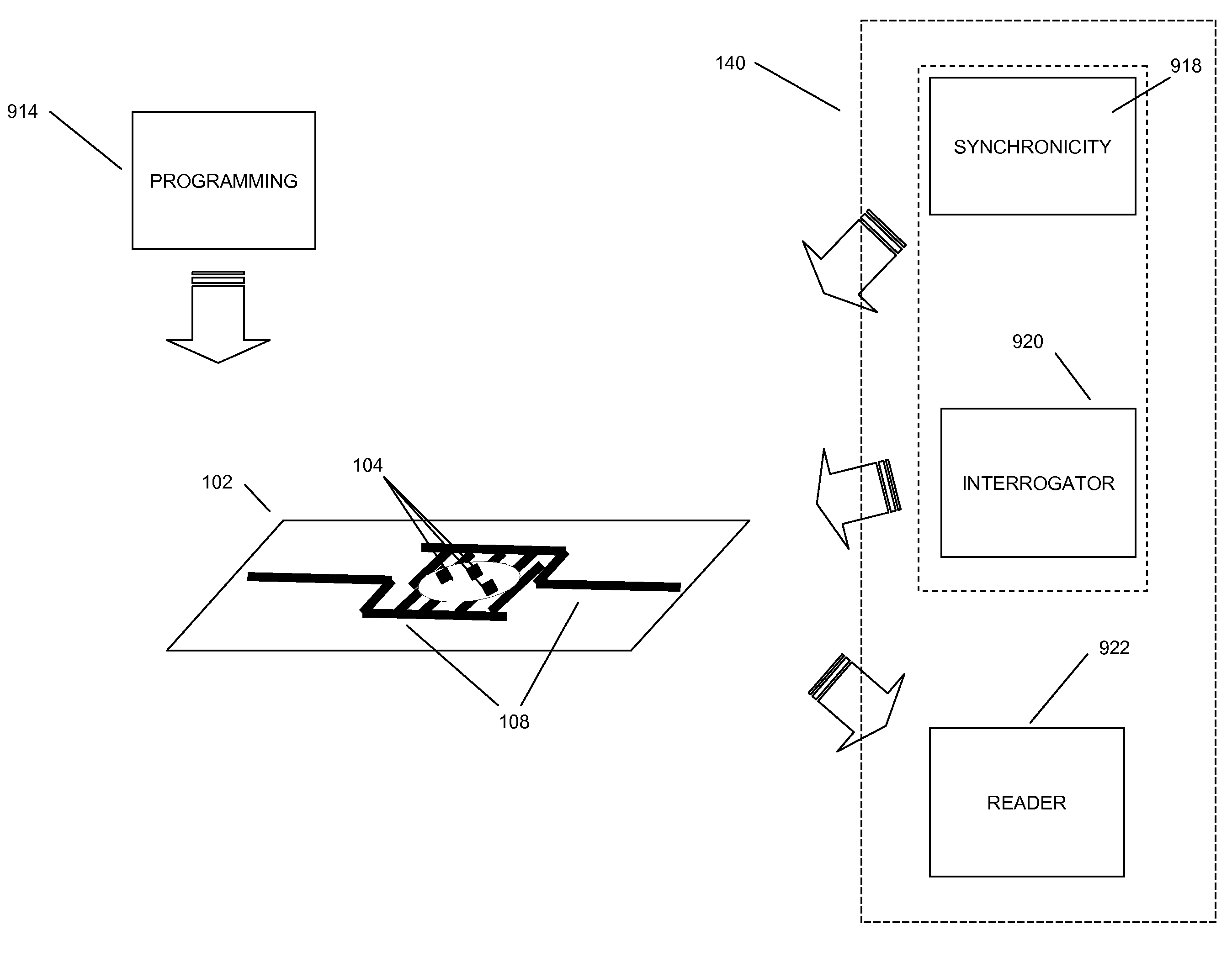
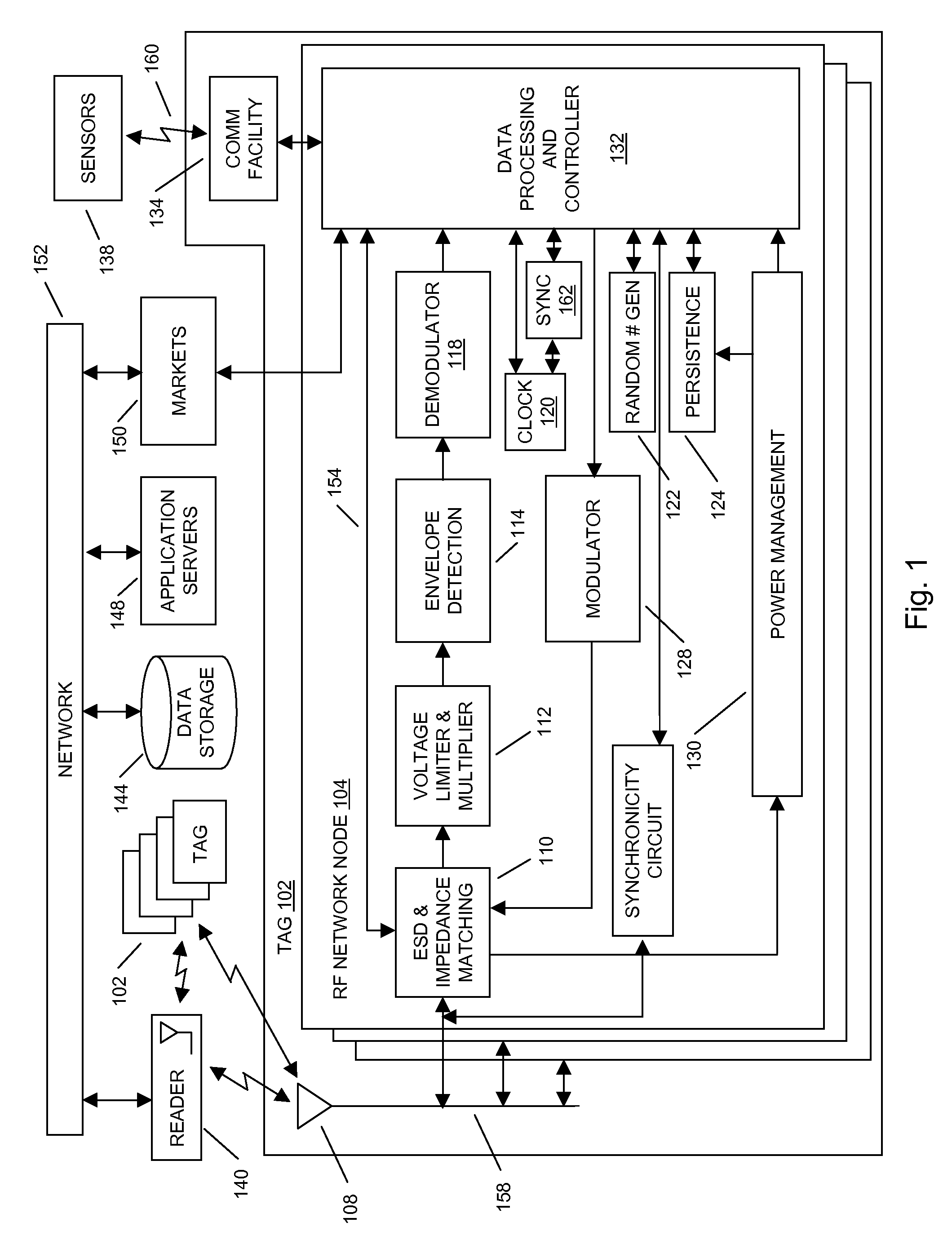
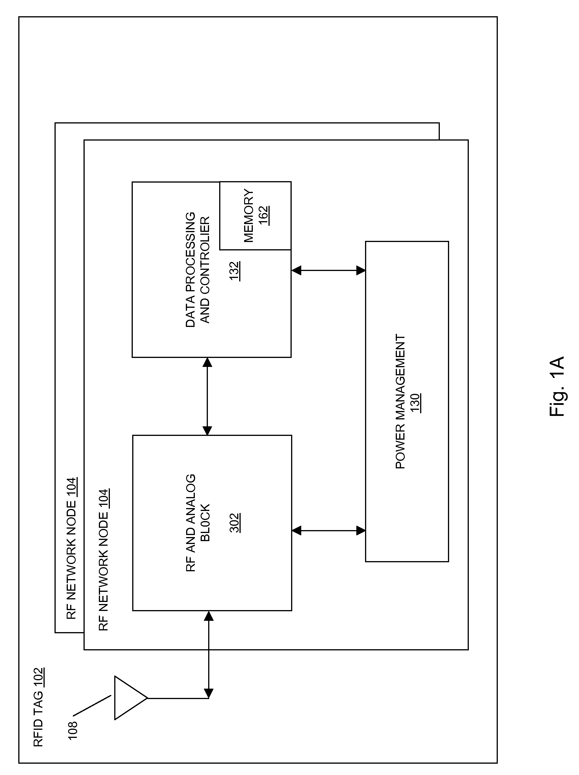
[0369]In aspects of the systems and methods described herein, a radio frequency identification (RFID) tag may use multiple RF network nodes (e.g. radio microchips) to communicate information to a RFID reader, a network, other RFID network nodes, or the like. The communication of the information may be provided to the RFID reader using at least one antenna, using a communication facility, using both the at least one antenna and the communication facility, or the like.

[0370]In aspects of the systems and methods described herein, each of the multiple RF network nodes may include radio frequency circuits, digital circuits, memory storage, communication facilities, and the like for storing and transmitting information to RFID readers, networks, other RFID tags, markets, applications, data stores, and the like. The RFID tag may include circuitry for inter RF network node communication that may provide RF network node redundancy, increased functionality, improved connectivity to the reader...


PUM


Abstract

In embodiments of the present invention improved capabilities are described for a Radio Frequency ID (RFID) tag that contains multiple Radio Frequency (RF) network nodes that may include memory storage for the RFID tag, the memory storage may include one time programmable (OTP) memory and many time programmable (MTP) memory and the storage of the information may be within the OTP and MTP memory.

Description

CROSS-REFERENCE TO RELATED APPLICATIONS[0001]This application claims the benefit of the following provisional applications, each of which is hereby incorporated by reference in its entirety: U.S. Provisional Application 60 / 868,107, filed Dec. 1, 2006; and U.S. Provisional Application 60 / 915,838 filed May 3, 2007.[0002]This application also is a continuation-in-part of U.S. patent application Ser. No. 11 / 609,277 filed Dec. 11, 2006 which claims the benefit of the following provisional applications: U.S. Provisional Application 60 / 749,645, filed Dec. 9, 2005; U.S. Provisional Application 60 / 803,610, filed May 31, 2006; and U.S. Provisional Application 60 / 803,612, filed May 31, 2006. Each of these applications is incorporated herein by reference in its entirety.BACKGROUND[0003]1. Field[0004]The invention relates to a Radio Frequency ID (RFID) tags that contain multiple Radio Frequency (RF) network nodes that provide enhanced memory capabilities, redundant functionality, and multiple fr...

Claims


Application Information

Patent Timeline
IPC IPC(8): H04Q5/22
CPCG06K19/0723G08B13/2431H04L67/12G08B21/22H04L67/04G08B19/00
Inventor BUTLER, TIMOTHY P.BERRIOS, JAVIERBECKHARDT, STEVEHAMLIN, ROBERT W.MOORE, LARRYPULESTON, DAVID
Owner TEGO INC
Learn More