
Vision enhancement device for use in vehicle

a technology for enhancement devices and vehicles, applied in anti-theft devices, instruments, transportation and packaging, etc., can solve problems such as confusion, and achieve the effect of improving the visual recognition of operation and simple manner

Inactive Publication Date: 2008-08-07
HONDA MOTOR CO LTD
View PDF6 Cites 12 Cited by
  • Summary
  • Abstract
  • Description
  • Claims
  • Application Information

AI Technical Summary

Benefits of technology

[0009]It is an object of the present invention to provide a vision enhancement device for use in a vehicle which can improve the visual recognition of operation while maintaining the line of sight of the operator in a position that is appropriate for operation, and which can inform the operator of the state of the vehicle in a simple manner.
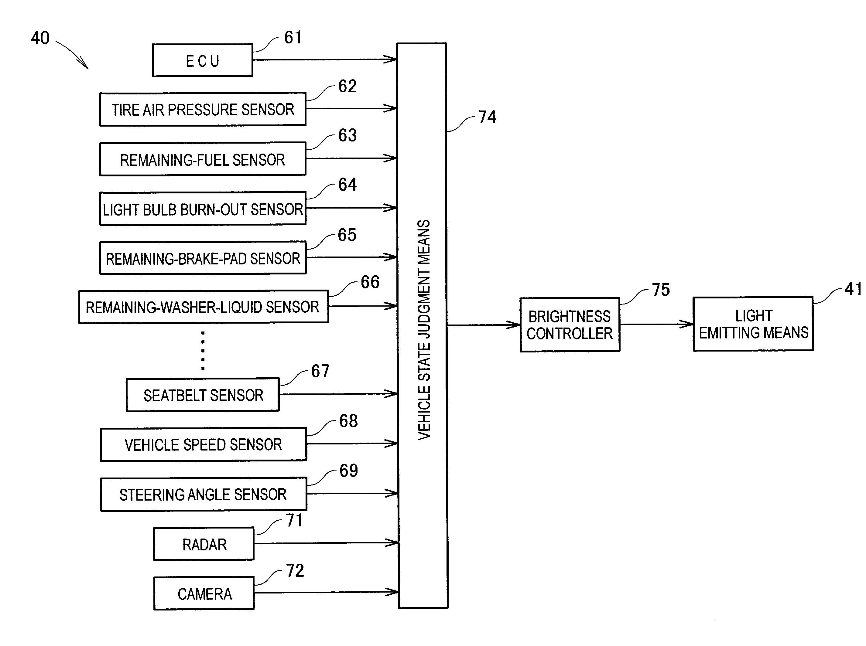
[0012]The first light emitting means is caused to emit light in accordance with changes in the vehicle state and environment surrounding the vehicle, and caused to show this light on the windshield, whereby the operator can be informed that there have been changes in the vehicle state or environment surrounding the vehicle. Specifically, the dividing means is a false image generating means which is disposed beneath the windshield, and forms a substantially rectilinear false image that can be recognized in a substantially rectilinear manner from the vantage point position of the operator. The dividing means comprises first light emitting means is caused to emit light more brightly in one portion of the substantially rectilinear false image than in another portion. Accordingly, the operator can be quickly informed of diverse types of vehicle information without their visual field of the operator being altered.
[0013]Preferably, the false image generating means comprises dividing lines formed on an instrument panel disposed beneath the windshield. Accordingly, the dividing lines formed on the instrument panel will be reflected in the windshield, which can be divided into a plurality of regions. As a result, the false image generating means can be readily constructed.
[0014]Desirably, the false image generating means comprises second light emitting means for forming a substantially rectilinear false image that can be recognized in a substantially rectilinear manner from the vantage point position of the operator. This second light emitting means can also transmit diverse types of vehicle information without the visual field of the operator being altered.
[0015]In a preferred form, the second light emitting means emits light of a color that differs from that of the first light emitting means. Accordingly, the types of information transmission can be increased.
[0016]The first and second light emitting means may be constructed such that at least a portion of these means are capable of flashing. As a result of this flashing, the types of information transmission can be further increased.

Problems solved by technology

Furthermore, in the abovementioned head-up display 200, the content of the display is diverse, which can create a sense of confusion.

Method used


Image

  • Vision enhancement device for use in vehicle
  • Vision enhancement device for use in vehicle
  • Vision enhancement device for use in vehicle

Examples


first embodiment

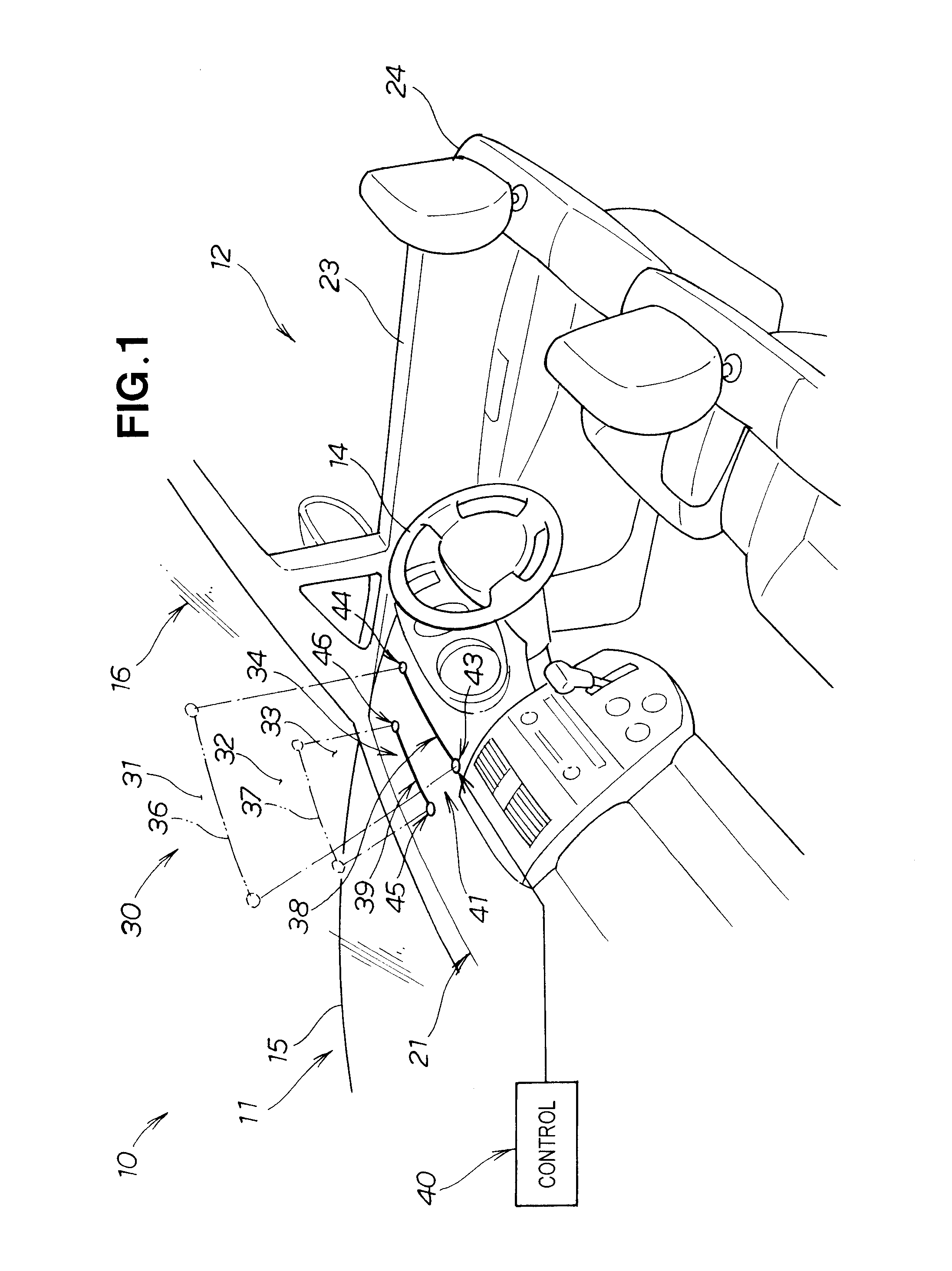
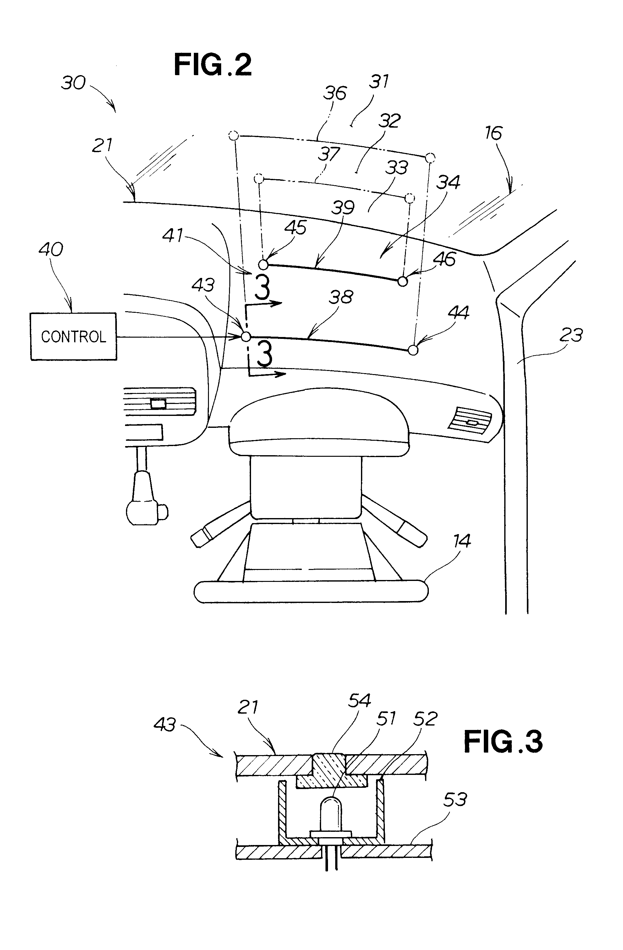
[0034]Reference is now made to FIGS. 1 through 7 showing a vision enhancement device for use in a vehicle according to the present invention.

[0035]A vehicle 10 shown in FIGS. 1 and 2 comprises a steering wheel 14 for steering a vehicle body 11; a hood 15 for covering a front part of the vehicle body 11; a windshield (front window) 16 for covering a front part of a passenger compartment 12 in a transparent manner; a roof 17 (see FIG. 6) for covering an upper part of the passenger compartment 12; an instrument panel 21 disposed in a front part of the passenger compartment 12; doors 23 for covering side surfaces of the passenger compartment 12; a vehicle seat 24 in which the operator (occupant) 18 (see FIG. 6) is seated; and a vision enhancement device 30 for use in a vehicle to enhance vision so that the line of sight of the operator 18 is maintained in an appropriate position during operation.

[0036]The vision enhancement device 30 for use in a vehicle comprises dividing means 34 for ...

second embodiment

[0060]FIG. 8 shows the vision enhancement device.

[0061]The vision enhancement device 80 shown in FIG. 8 comprises dividing means 84 for dividing the windshield 16 substantially horizontally into a plurality of areas; i.e., a first area 81, a second area 82, and a third area 83, and a control part 90 for controlling the first light emitting means 91 and second light emitting means 92.

[0062]The dividing means 84 constitutes false image generating means, which is disposed beneath the windshield 16, and which shows an upper false image line 86 and a lower false image line 87 on the surface of the windshield 16.

[0063]The false image generating means 84 preferably comprises first and second dividing lines 88 and 89 disposed on an instrument panel 85, first light emitting means 91 comprising four light emitting bodies 93, 94, 95, and 96 disposed on either end parts of the first and second dividing lines 88 and 89, and second light emitting means 92 disposed on intermediate parts of the fir...

third embodiment

[0067]FIG. 9 shows the vision enhancement device 100.

[0068]The vision enhancement device 100 of the third embodiment comprises dividing means 104 for dividing the windshield 16 substantially horizontally into a plurality of areas (first through third areas) 101 through 103 and a control part 110 for controlling the first and second light emitting means 111 and 112 of the dividing means 104.

[0069]The dividing means 104, which is disposed below the windshield 16, constitutes false image generating means for showing an upper false line 106 and lower false line 107 on the windshield 16.

[0070]The false image generating means 104 preferably comprises first light emitting means 111 comprising a light emitting unit 113 consisting of numerous light emitting bodies (light emitting diodes) densely lined up in the form of a line on a substrate disposed on an instrument panel 105, and second light emitting means 112 comprising a light emitting unit 114 similarly comprising numerous light emittin...


PUM


Abstract

A vision enhancement device for use in a vehicle that improves the frontward vision of an operator during operation. The device has two dividing lines set apart from each other on an instrument panel. These dividing lines show as false image lines on an inside surface of a front window, and divide the inside surface of the front window into a plurality of areas in a vertical direction. A second area formed between these two false image lines forms an appropriate visual field range when the operator looks forward while operating the vehicle. First light emitting means comprising light emitting diodes are disposed at both ends of each of the two dividing lines. The light emitted by these light emitting diodes is directed onto the front window as a false image in accordance with changes in the vehicle state and the environment around the vehicle.

Description

FIELD OF THE INVENTION[0001]The present invention relates to a vision enhancement device which can be used in a vehicle, which can improve vision in a predetermined area of the windshield (front window), and which can quickly improve the recognition of operating conditions and the like.BACKGROUND OF THE INVENTION[0002]In recent years, there have been attempts to improve visual recognition of various types of vehicle information without disrupting the attitude (line of sight) of the operator in vision enhancing devices for use in a vehicle.[0003]In vision enhancing devices of this type for use in a vehicle, priority is given to ensuring a sufficient visual field from the windshield, and a head-up display for use in a vehicle, which reflects operating information and the like on the windshield, is used in order to allow quick recognition of the state of the vehicle during operation.[0004]Such a head-up display is disclosed in Japanese Patent Application Laid-Open Publication No. 8-227...

Claims


Application Information

Patent Timeline
IPC IPC(8): B60Q1/00B60K35/00G02B27/01G08G1/16
CPCB60K35/00G02B2027/0141G02B27/01B60K35/60B60K2360/785
Inventor UEMATSU, HIROSHIKISHIMOTO, YUYA
Owner HONDA MOTOR CO LTD
Learn More