Self contained container tracking device

Inactive Publication Date: 2008-08-07
MILLS IAN MICHAEL
6 Cites 47 Cited by

AI-Extracted Technical Summary

Problems solved by technology

Unfortunately, these approaches have problems including: key distribution to recipients and/or loss of the key in transit to open the lock; custom requirements to inspect the locked container's contents upon arrival at a port; and the possibility that forced entry will occur through means other than the door, such as by removal of door hinges, access pins, prying of side panels and the like.
These systems typically lack ...

Abstract

A system for tracking the locations of a freight container using a self contained and portable container tracking device is described.
The container tracking device includes a GPS receiver, an attachment mechanism to easily secure the tracking device to the interior of a container door, an intrusion detection system and an alarm. The user can access the position and status information through a web site Internet access to a centralized database, SMS interrogation or SMS message updates.
The user can load map information, trip alarm conditions, update method, as well as authentication information on a flash drive and insert it in the tracking device.
In the event an alarm condition is broken, an alarm is triggered and an alarm message is sent to the user.
The tracking device is located inside the container whereas its antennas are located on the outside. This prevents damage, tampering and theft of the tracking device.

Application Domain

Burglar alarm with fastening tamperingRadio/inductive link selection arrangements +3

Technology Topic

Intrusion detection systemCentralized database +8

Image

  • Self contained container tracking device
  • Self contained container tracking device
  • Self contained container tracking device

Examples

  • Experimental program(1)

Example

[0037]Similar reference numerals are used in different figures to denote similar components.
DETAILED DESCRIPTION OF THE PREFERRED EMBODIMENTS
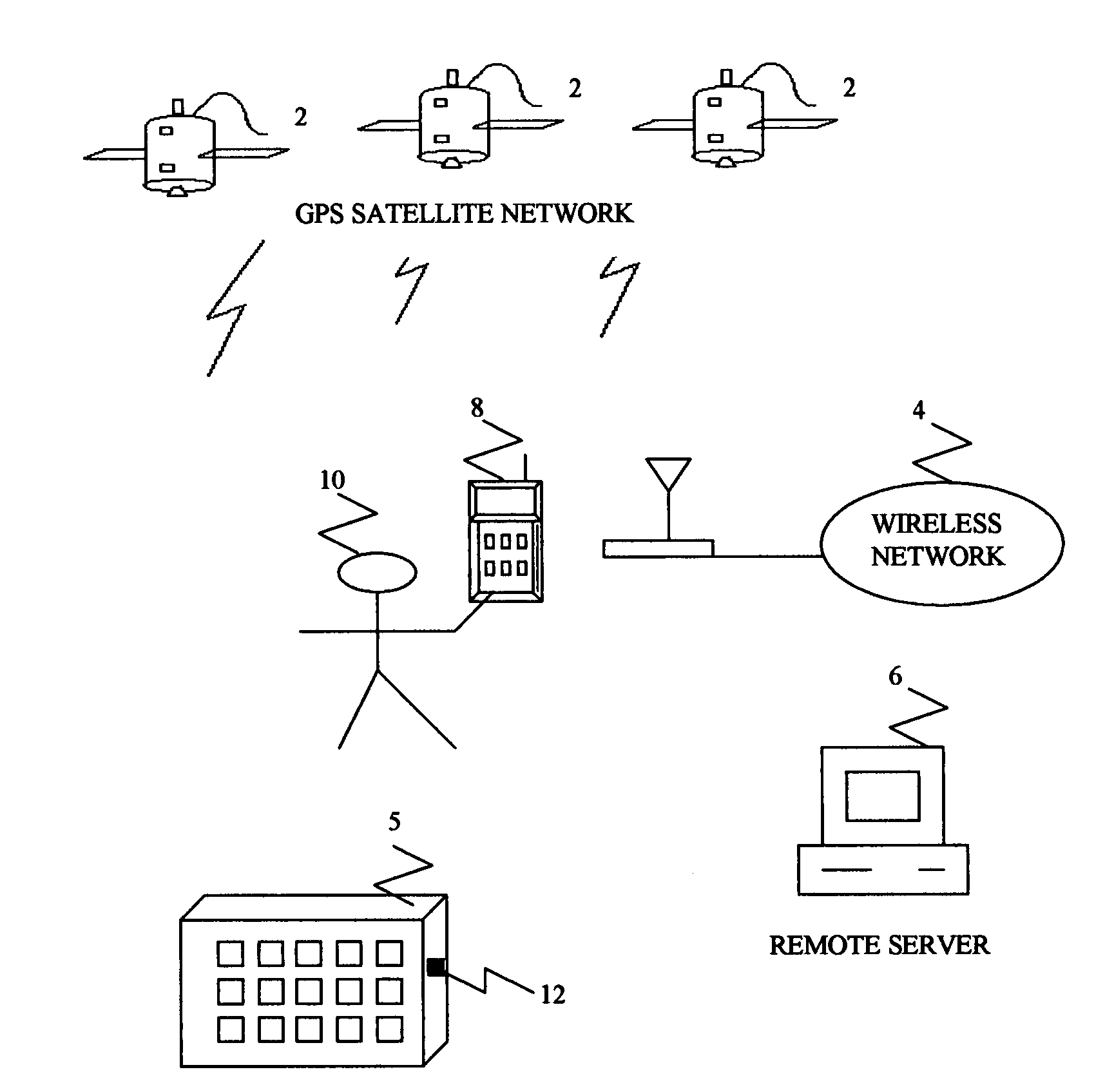
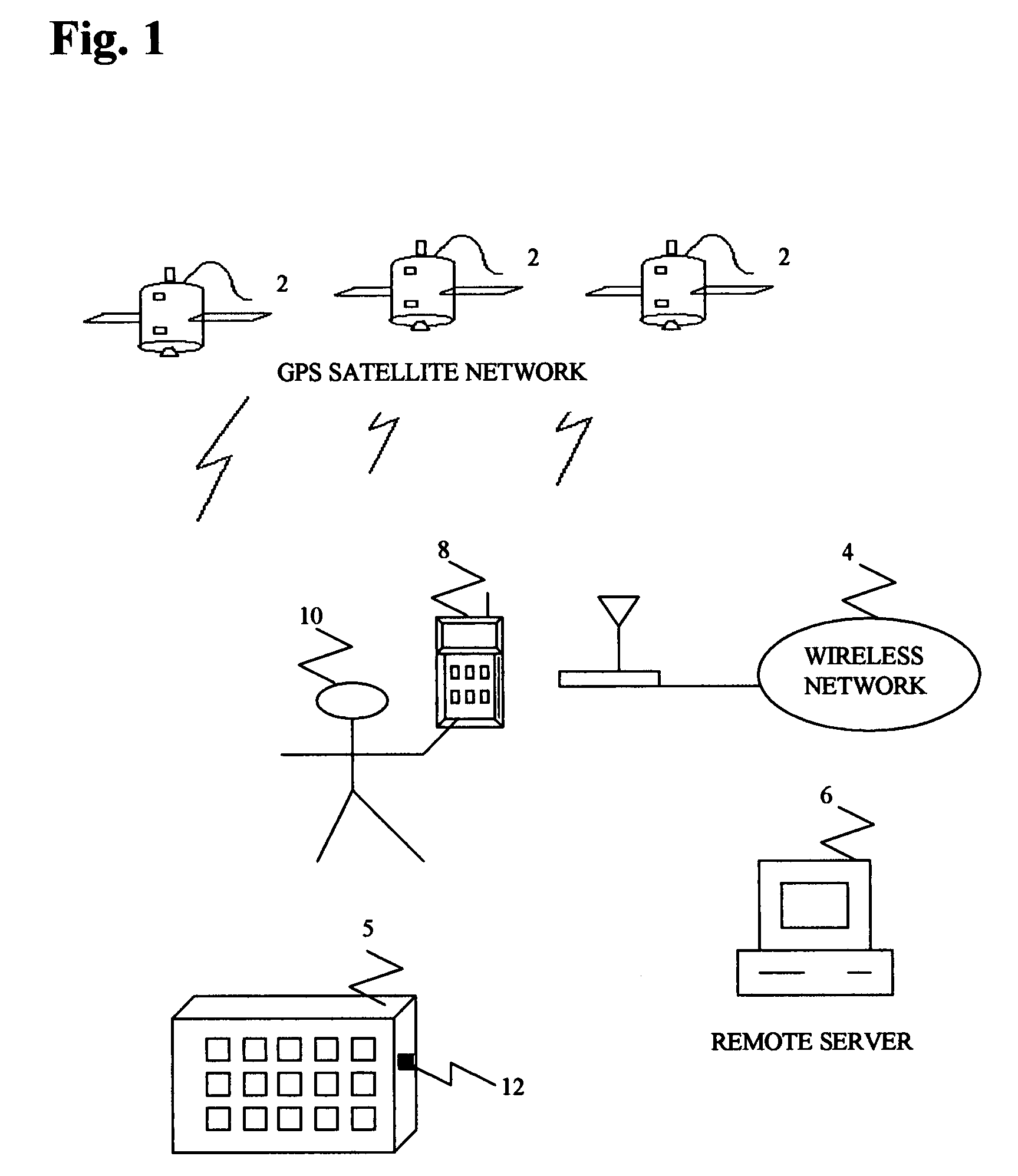
[0038]Referring to FIG. 1, a container 5 equipped with a container tracking device 12 collaborates with GPS constellation 2 to determine position information.
[0039]Container tracking device 12 collaborates with wireless network 4 to receive commands and to send position information to user 10 either through remote server 6 or mobile unit 8.
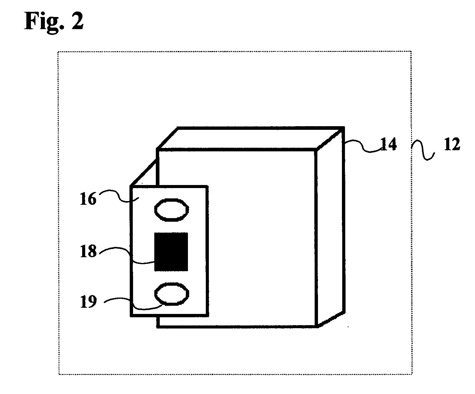
[0040]Referring to FIG. 2, container tracking device 12 comprises restraint unit 16 used to attach the container tracking device housing 14 to a container door. Restraint unit 16 comprises an antenna system for the GPS and wireless transceiver systems as well as mechanism 19 for fastening the bracket to the container door.
[0041]FIG. 3 is a schematic illustrating a container tracking device 12 installed on a container door 30, whereby housing 14 is positioned adjacent to the container door, on the inside of the container, and restraint unit 16 with antennas for GPS and cellular receivers is positioned to the outside of the container.
[0042]Referring now to FIG. 4, in one embodiment, container tracking device housing 14 comprises a processor 40 interconnected with GPS receiver 41, cellular transceiver 42, sensors 45, alarm 46, battery 44 and slot 47 for removable flash drive 48. Alternatively, the container tracking device may comprise a key pad 43.
[0043]GPS receiver 41 may be a GSP, GLONASS, LORAN, GNSS, or any other commercially available service, or combination of services, which provide global position information.
[0044]Cellular transceiver 42 may be any cellular receiver capable of SMS or GPRS.
[0045]SMS is Short Message Service. It is available on wireless networks allowing text messages of up to 160 characters to be sent and received via the network operator's message center to a mobile phone/portable terminal, or from the Internet, using a so-called “SMS gateway” website. If the mobile phone/portable terminal is powered off or out of range, messages are stored in the network and are delivered at the next opportunity.
[0046]GPRS is General Packet Radio Service, a data transmission technique that transmits and receives data in packets between portable terminals/mobile phones or between a portable terminal/mobile phone and a second terminal.
[0047]Sensors 45 may be any sensors for detecting intrusion, door opening, motion, temperature, sound, beam crossing, light, acceleration, or any other conditions. Sensors 45 may be locks, actuators, motors, contact switches/sensors, reed switches, buttons, infrared/ultrasound sensors, heat sensors, light sensors, acceleration sensors, or any other sensors capable of detecting intrusion.
[0048]Alarm 30 may be a loud alarm with more than 85 decibels.
[0049]Battery 44 provides power to some of the components of container tracking device 12. It will be understood that battery 44 may be nickel-cadmium, lithium, alkaline or nickel-hydride battery or any other portable source of electric power.
[0050]Flash drive 4 may be a USB flash or any portable storage device or memory device. Flash drive 4 holds user configuration information such as:
[0051]operation modes,
[0052]alarm conditions,
[0053]location names database,
[0054]alert method,
[0055]sensor thresholds,
[0056]alarm thresholds,
[0057]authorized passwords,
[0058]authorized load/unload zones,
[0059]authorized checkpoints, and any other information.
[0060]Configuration information is loaded onboard flash drive 4 through a standard computer system.
[0061]A software application may be used to collect information from the user and to organize data on flash drive 4 in a way that processor 40 may interpret it.
[0062]A software application may also be used to organize and load map information on flash drive 40.
[0063]In an alternative embodiment, key pad 43 is used to authenticate the user against authentication reference data obtained from flash drive 4 or obtained through SMS messaging.
[0064]As described hereafter, processor 40 reads configuration information off a flash drive 48 inserted in slot 47. Slot for flash drive 47 can be a USB slot or any connector compatible with removable flash drive 48.
[0065]Processor 40 may activate tracking device 12 on detection of insertion of Flash drive 48 into slot 47 aboard the tracking device 12.
[0066]Processor 40 obtains location information from GPS receiver 41 and may correlate it to location names from flash drive 48.
[0067]Processor 40 may receive trigger events through cellular transceiver 42. It sends location information through cellular transceiver 42.
[0068]In an alternative embodiment, on receipt on an SMS message, processor 40 replies with a new SMS message containing location and/or status information.
[0069]In an alternative embodiment, on receipt on an SMS message containing data, processor 40 authenticates the message data then replies with a new SMS message containing location and/or status information.
[0070]In an alternative embodiment, on receipt on an SMS message containing instructions, processor 40 executes said instructions. Said instructions may indicate reporting position to a specific phone number such as police station or to a number of phone numbers.
[0071]Processor 40 may periodically send position and/or status information to a destination number.
[0072]Processor 40 may transfer data through data packets, data stream, voice information, file transfer or any other data transfer method.
[0073]Processor 40 monitors sensors 45 to detect exception events such as intrusion, deviation from a path, abnormal driving, accident, abnormal conditions such as high temperature, or any condition that is a cause for concern. Processor 40 may compare sensor 45 data against user thresholds established in flash drive 48. On deviation from user thresholds, an alarm mode is entered.
[0074]In alarm mode, onboard alarm 30 may be activated. SMS messages may be sent. Also, phone numbers may be called and messages played.
[0075]When container tracking device 12 is not in operation it remains in a dormant state (“sleep-mode”) to conserve the energy of battery 44.
[0076]FIG. 5 is an alternative container tracking device whereby restraint unit 50 extends outwards and to the side of the housing and allows inserting tracking device 12 between both container doors when closing the container doors. This system allows fastening the tracking device to both container doors through mechanism 52.
[0077]FIG. 6 is an alternative container tracking system whereby restraint unit 62 rotates around an axis 64 and allows fastening the tracking device to both container doors. The device has an extended part 60 and fastening mechanism 66 that allows securing the tracking device against the both container doors.
[0078]FIG. 7 is a container tracking system composed of a first unit 70 containing a tracking device and a second unit 72 containing antennas 74. Unit 70 and 72 are tied together using a flexible belt 76.
[0079]To attach the system, the user opens the two container doors slightly, inserts unit 70 behind the two container doors through the main opening. Unit 70 is placed towards the inside of the container, belt 76 is placed between the two container doors and unit 72 is placed to the exterior of the container. The user closed the container doors and slides unit 2 along the belt until the whole system grips to the container doors. Pin 78 is inserted through unit 2 to seal the system.
[0080]Numerous other modifications, variations, and adaptations may be made to the particular embodiment of the invention described above without departing from the scope of the invention, which is defined in the claims. Hence, while exemplary embodiments of the present invention have been set forth above, it is to be understood that the pioneer inventions disclosed herein may be constructed or used otherwise than as specifically described.

PUM

no PUM

Description & Claims & Application Information

We can also present the details of the Description, Claims and Application information to help users get a comprehensive understanding of the technical details of the patent, such as background art, summary of invention, brief description of drawings, description of embodiments, and other original content. On the other hand, users can also determine the specific scope of protection of the technology through the list of claims; as well as understand the changes in the life cycle of the technology with the presentation of the patent timeline. Login to view more.
Why Eureka
Try Eureka