
Image processing apparatus, image forming apparatus, and control method thereof

a technology of image processing and forming apparatus, which is applied in the direction of visual presentation, instruments, printing, etc., can solve the problems of unwanted highlighting of low frequency components of an image generated by a plurality of scans, and achieve the effect of high-quality images

Active Publication Date: 2008-08-07
CANON KK
View PDF10 Cites 22 Cited by
  • Summary
  • Abstract
  • Description
  • Claims
  • Application Information

AI Technical Summary

Benefits of technology

The present invention relates to an image forming apparatus and an image processing apparatus that form images by scanning a printing head on a printing medium. The invention aims to improve the quality of the formed images by reducing graininess and improving the phase relationship between dots in a low-frequency region. The technical effect of the invention is to provide a high-quality image with reduced graininess and improved clarity.

Problems solved by technology

However, with the scheme described in aforementioned patent reference 1, since the dot allocations among the main scans have low correlation, low frequency components of an image generated by the plurality of scans are unwantedly emphasized.

Method used


Image

  • Image processing apparatus, image forming apparatus, and control method thereof
  • Image processing apparatus, image forming apparatus, and control method thereof
  • Image processing apparatus, image forming apparatus, and control method thereof

Examples


first embodiment

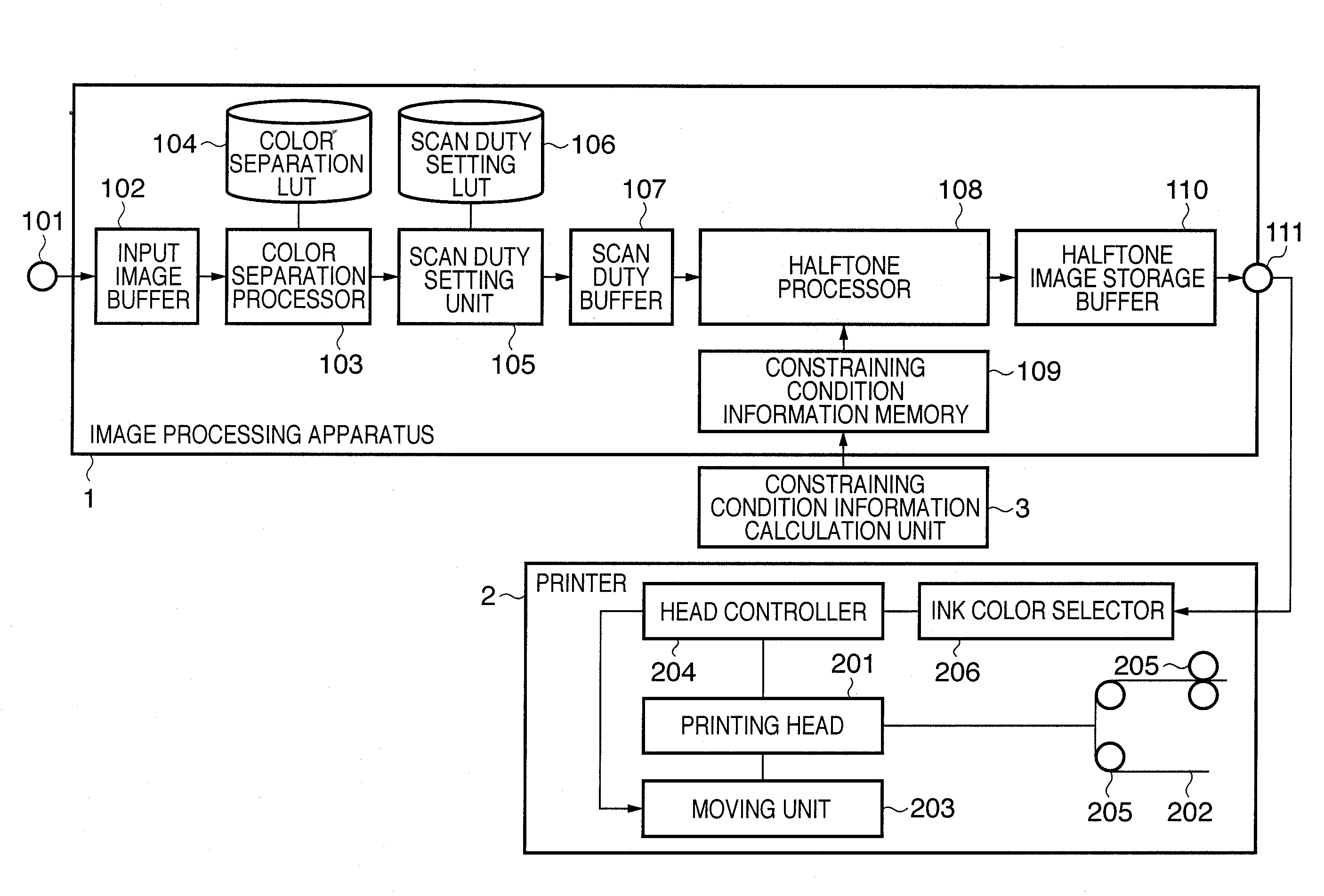
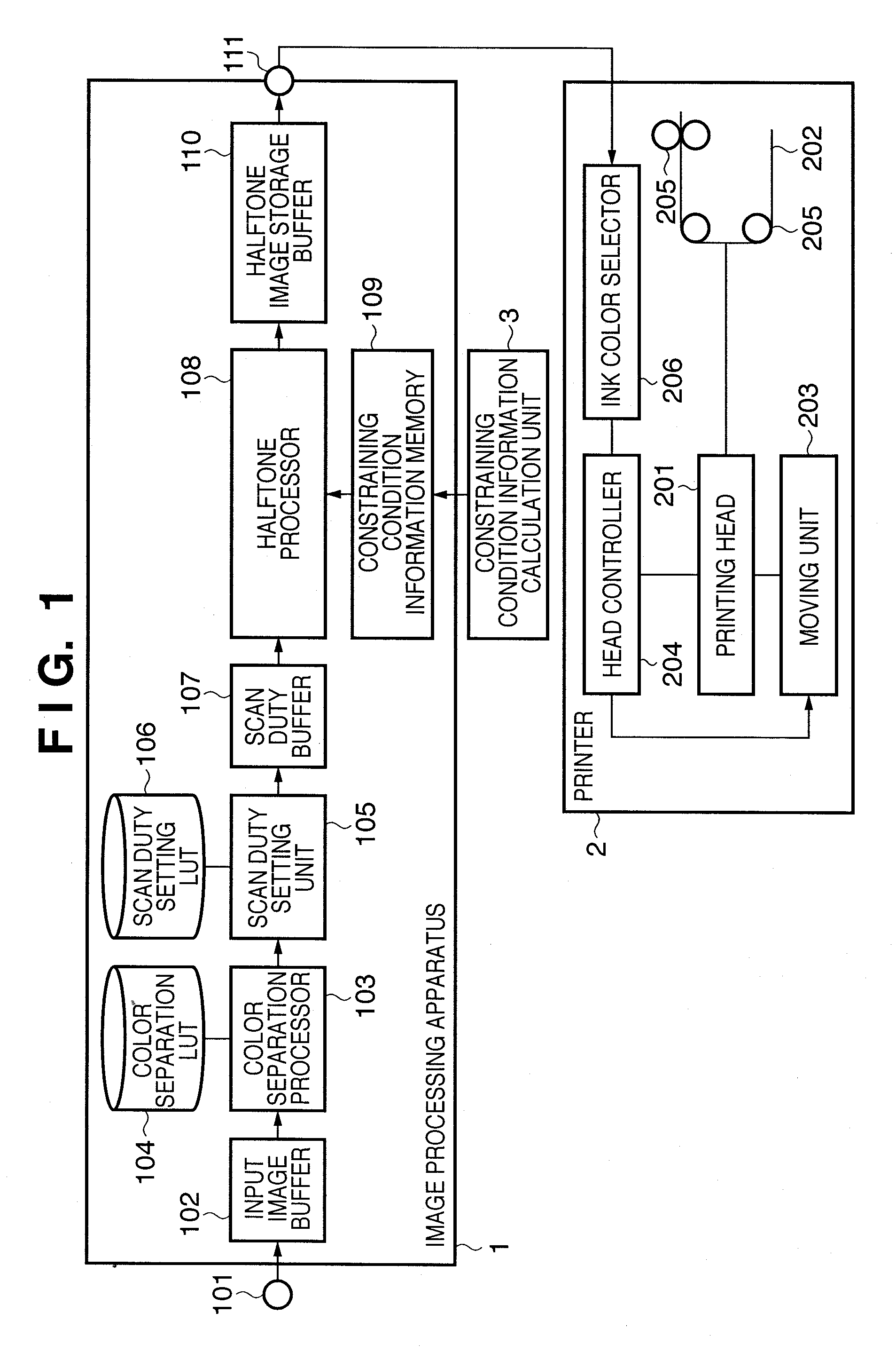
[0052]FIG. 1 is a block diagram showing the arrangement of an image forming system according to this embodiment. Referring to FIG. 1, reference numeral 1 denotes an image processing apparatus; 2, a printer; and 3, a constraining condition information calculation unit. Note that the image processing apparatus 1 can be implemented by, e.g., a printer driver installed in a general personal computer. In this case, respective units of the image processing apparatus 1 to be described below are implemented when the computer executes a predetermined program. As another arrangement, for example, the printer 2 may include the image processing apparatus 1, or the constraining condition information calculation unit 3 may be included in the image processing apparatus 1.

[0053]The image processing apparatus 1 and printer 2 are connected to each other via a printer interface or circuit. The image processing apparatus 1 receives image data to be printed from an image data input terminal 101, and sto...

second embodiment

[0182]The second embodiment according to the present invention will be described hereinafter. The first embodiment has exemplified a case in which the halftone processor 108 executes the error diffusion processing. The second embodiment will exemplify a case in which the dither matrix method is used in place of the error diffusion method. As described above, since the dither matrix method can speed up the processing compared to the error diffusion method, the second embodiment can attain high-speed processing. Furthermore, since the second embodiment uses the same constraining condition information as in the first embodiment, the same effects as those of the first embodiment can be obtained.

[0183]The detailed arrangement of the image forming apparatus of the second embodiment is the same as that in the first embodiment, except for the halftone processor 108. For the sake of simplicity, details of cyan halftone processing for 4-pass printing and the scan number k=1 as in the first em...


PUM


Abstract

In order to form a high-quality image, upon execution of multi-pass printing using a printing head with a plurality of nozzles, an image processing apparatus calculates, using a scan duty setting unit (105), scan duty data for respective nozzles for each scan of the printing head in accordance with input image data. A halftone processor (108) generates a dot pattern to be formed by applying N-ary processing. The constraining condition information is set so that the phase of spatial frequencies of a next dot pattern to be generated has an opposite phase relationship in a low frequency region with respect to the already printed dot pattern.

Description

BACKGROUND OF THE INVENTION[0001]1. Field of the Invention[0002]The present invention relates to an image processing apparatus, image forming apparatus, and control method thereof and, more particularly, to an image processing apparatus, image forming apparatus, and control method thereof, which form an image using the number of tones smaller than that of an input image.[0003]2. Description of the Related Art[0004]As image output apparatuses for wordprocessors, personal computers, facsimile apparatuses, and the like, printing apparatuses which print information of desired text, images, and the like on sheet-like printing media such as paper sheets, films, and the like are used. Such printing apparatuses adopt various printing schemes. Of these schemes, schemes for forming an image on a printing medium by attachment of printing agents are popularly put into practical use. As a representative example of such schemes, an ink-jet printing scheme is known.[0005]A printing apparatus, whic...

Claims


Application Information

Patent Timeline
Patent Type & Authority Applications(United States)
IPC IPC(8): B41J2/205
CPCH04N1/405G06K15/107
Inventor YANAI, TOMOKAZUUSHIRODA, ATSUSHI
Owner CANON KK
Learn More