
Printing control apparatus, printing apparatus, and printing contol method

a printing control and control apparatus technology, applied in printing, other printing apparatus, etc., can solve the problems of plurality of nozzle groups corresponding to ink of the same color, differences in print quality, and tendency to become significan

Active Publication Date: 2019-04-04
SEIKO EPSON CORP
View PDF0 Cites 1 Cited by
  • Summary
  • Abstract
  • Description
  • Claims
  • Application Information

AI Technical Summary

Benefits of technology

The invention provides a printing control apparatus, printing apparatus, and printing control method that can improve print quality stability and uniformity. The apparatus generates halftone data for driving nozzle groups in an uncorrelated manner, reducing differences in print quality between nozzle groups. This ensures consistent and high-quality printing results. Additionally, the apparatus can use either one of two nozzle groups for printing highlight portions to avoid deterioration of graininess. The halftone data is generated using either the dither method or the error diffusion method, ensuring uncorrelated driving of the nozzle groups.

Problems solved by technology

In such conventional art, differences in print quality between a case in which there is an error between nozzle groups and a case in which there is no error between nozzle groups in the plurality of nozzle groups corresponding to ink of the same color tend to become significant.

Method used


Image

  • Printing control apparatus, printing apparatus, and printing contol method
  • Printing control apparatus, printing apparatus, and printing contol method
  • Printing control apparatus, printing apparatus, and printing contol method

Examples


second embodiment

4. Second Embodiment

[0067]The embodiment described above is called the first embodiment. Next, a second embodiment will be described. In the second embodiment (and a third embodiment described later), elements that differ from the elements of the first embodiment are mainly described.

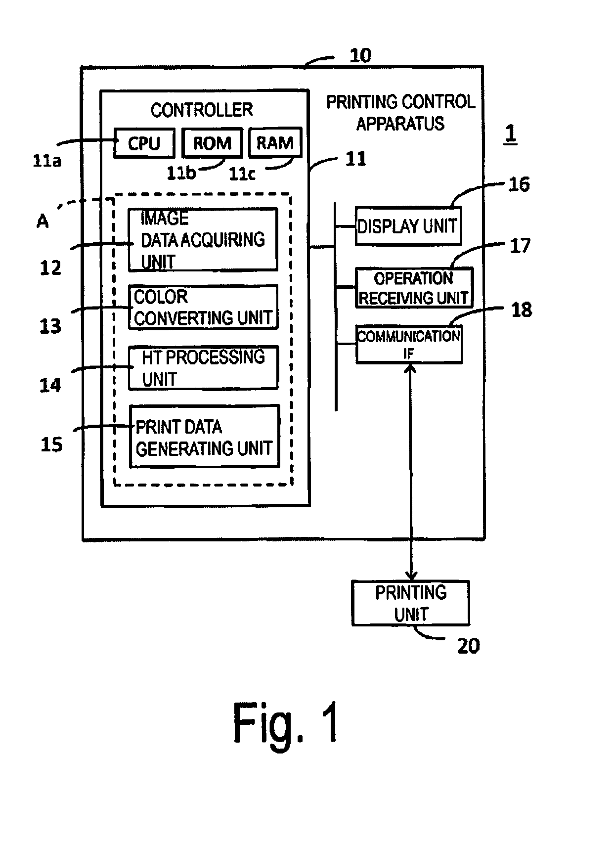
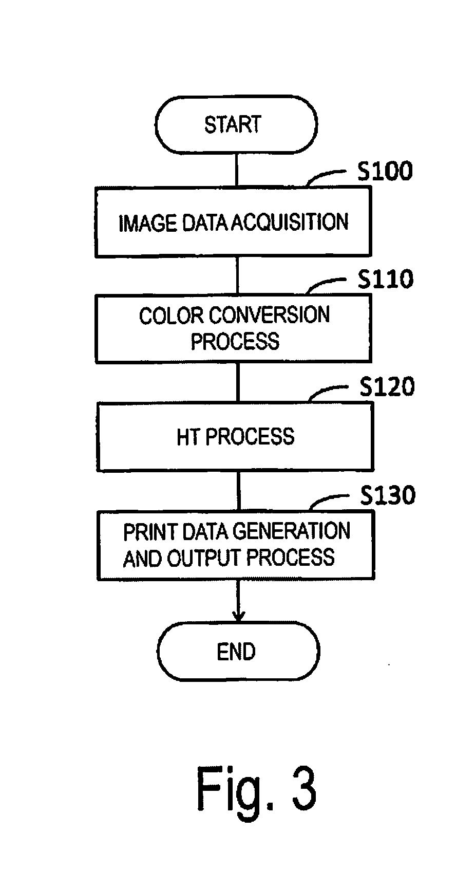
[0068]In step S120 of the second embodiment (FIGS. 3 and 4), the HT processing unit 14 executes the first HT process on the image data IM1 (step S121) and the second HT process on the image data IM1 (step S122) to generate the HTD1 for driving the first nozzle group and the HTD2 for driving the second nozzle group in an uncorrelated manner. At this time, the HT processing unit 14 generates the HTD1 and the HTD2 that drive only one of the first nozzle group and the second nozzle group corresponding to an image having a brightness of a predetermined highlight range in the image data IM1.

[0069]For example, the first dither mask applied to the image data IM1 in the first HT process (step S121) by the HT pro...

third embodiment

5. Third Embodiment

[0080]The print head 21 of the printing unit 20 may be configured to eject a plurality of sizes of dots having different volumes of liquid per droplet. For example, the print head 21 is configured to eject three types of dots of different sizes (large dots, medium dots, and small dots) from the nozzles 27. The volume per dot droplet of each different size is determined in advance by the design of the printing unit 20. Thus, the HT data (first HT data, second HT data) of each ink color generated by the HT processing unit 14 in step S120 is data that specifies whether the dot is ON (present) or OFF (absent) and, in a case where the dot is ON, whether the dot is a large dot, medium dot, or small dot.

[0081]FIG. 7 is a simplified diagram illustrating an example of the relationship between the driving waveform applied to one of the nozzles 27 (an actuator of the nozzle 27) of the print head 21, and the dots ejected and formed on the printing medium P by the one of the n...


PUM


Abstract

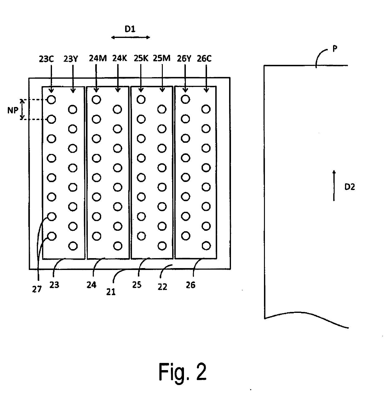
A printing control apparatus is configured to control printing using a print head provided with, on different head chips, a plurality of nozzle groups including a first nozzle group and a second nozzle group configured to eject ink of a same color, with at least a portion of a formation range of each of the nozzle groups overlapping each other. The different head chips is disposed in a direction that crosses an alignment direction of nozzles. The printing control apparatus includes a halftone processing unit configured to generate halftone data specifying a presence or absence of dots for each pixel serving as data to drive the nozzle groups based on image data. The halftone processing unit is configured to generate first halftone data to drive the first nozzle group and second halftone data to drive the second nozzle group in an uncorrelated manner.

Description

CROSS-REFERENCE TO RELATED APPLICATIONS[0001]This application claims priority to Japanese Patent Application No. 2017-191219 filed on Sep. 29, 2017. The entire disclosure of Japanese Patent Application No. 2017-191219 is hereby incorporated herein by reference.BACKGROUNDTechnical Field[0002]The invention relates to a printing control apparatus, a printing apparatus, and a printing control method.Related Art[0003]An ink jet color printing apparatus provided with rows of nozzles (nozzle rows) for ink that are symmetrically disposed on a print head is known. The nozzle rows are each dedicated to one of the ink colors, i.e., black (K), cyan (C), magenta (M), and yellow (Y), and are disposed in correspondence with each color in the order of KCMYYMCK along a movement direction of the print head (refer to FIG. 7 in JP-A-11-320926).[0004]When a plurality of nozzle rows corresponding to ink of the same color (K, for example) exist as in JP-A-11-320926, processing has been performed under the...

Claims


Application Information

Patent Timeline
IPC IPC(8): B41J2/21B41J2/045
CPCB41J2/2135B41J2/04505B41J2/04586B41J2/21B41J29/393B41J2/2054B41J2/51B41J2/04588B41J2/04581B41J2/04593B41J2/04573
Inventor HOSHII, JUN
Owner SEIKO EPSON CORP
Learn More