Camera module

a technology of camera module and holder, which is applied in the direction of dynamo-electric machines, dynamo-electric components, instruments, etc., can solve the problems of difficult space security, insufficient magnetic force of each magnet, etc., and achieve the effect of reducing the size of the camera module and sufficient driving force of the holder

Active Publication Date: 2008-08-07
MITSUMI ELECTRIC CO LTD
View PDF3 Cites 41 Cited by
  • Summary
  • Abstract
  • Description
  • Claims
  • Application Information

AI Technical Summary

Benefits of technology

[0010]The present invention has been made in view of the problems described above, and therefore it is an object of the present invention to provide a camera module that can provide a sufficient driving force of a holder even in the case where the entire size of the camera module is reduced.

Problems solved by technology

Therefore, when the entire size of the camera is to be reduced, there is a problem in that sufficient magnetic force cannot be secured in each of the magnets 102.
However, if the entire size of the camera module is to be further reduced, there arises another problem in that it becomes difficult to secure a space for providing the spring 105.

Method used


Image

  • Camera module
  • Camera module
  • Camera module

Examples


Embodiment Construction

[0028]A camera module according to an embodiment of the present invention will be described below with reference to the accompanying drawings.

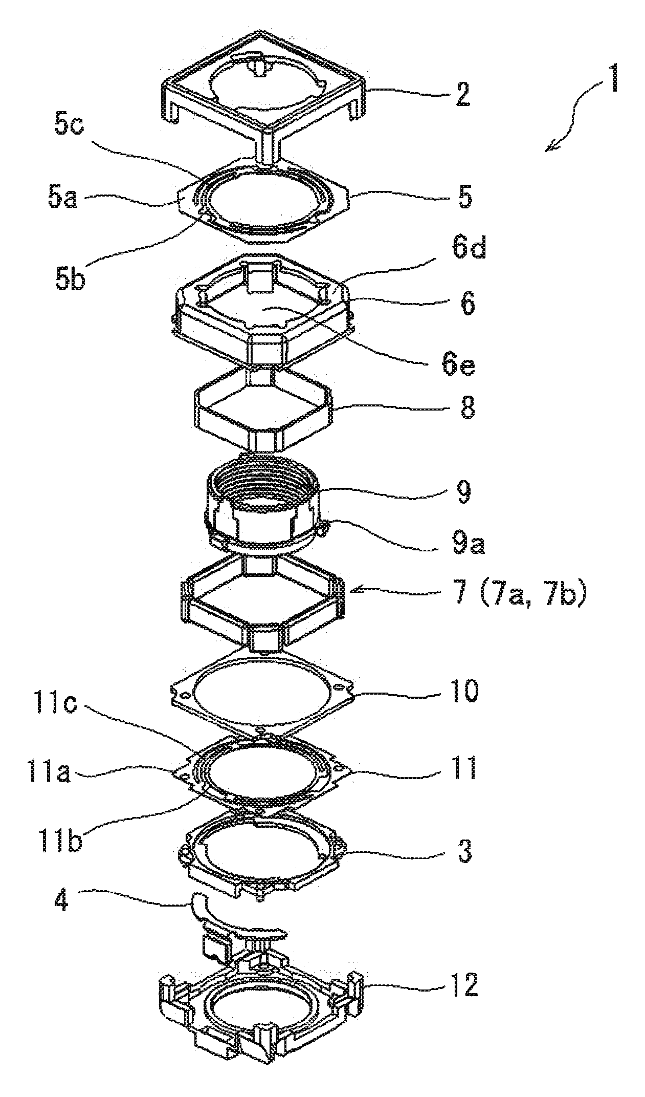
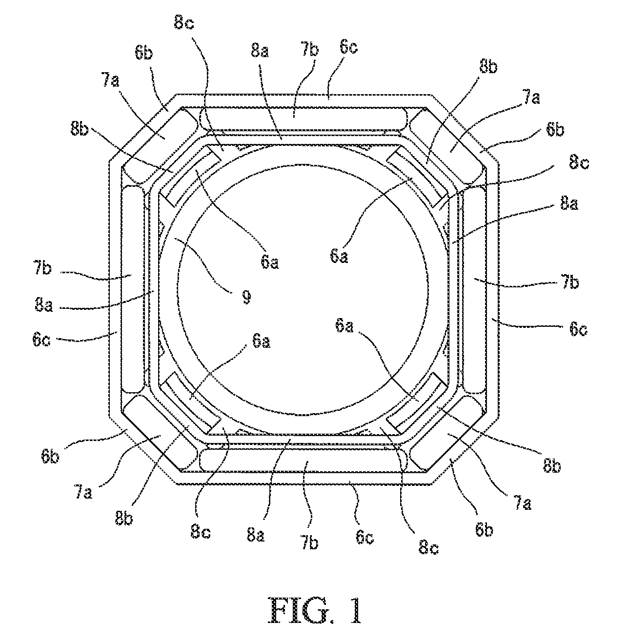
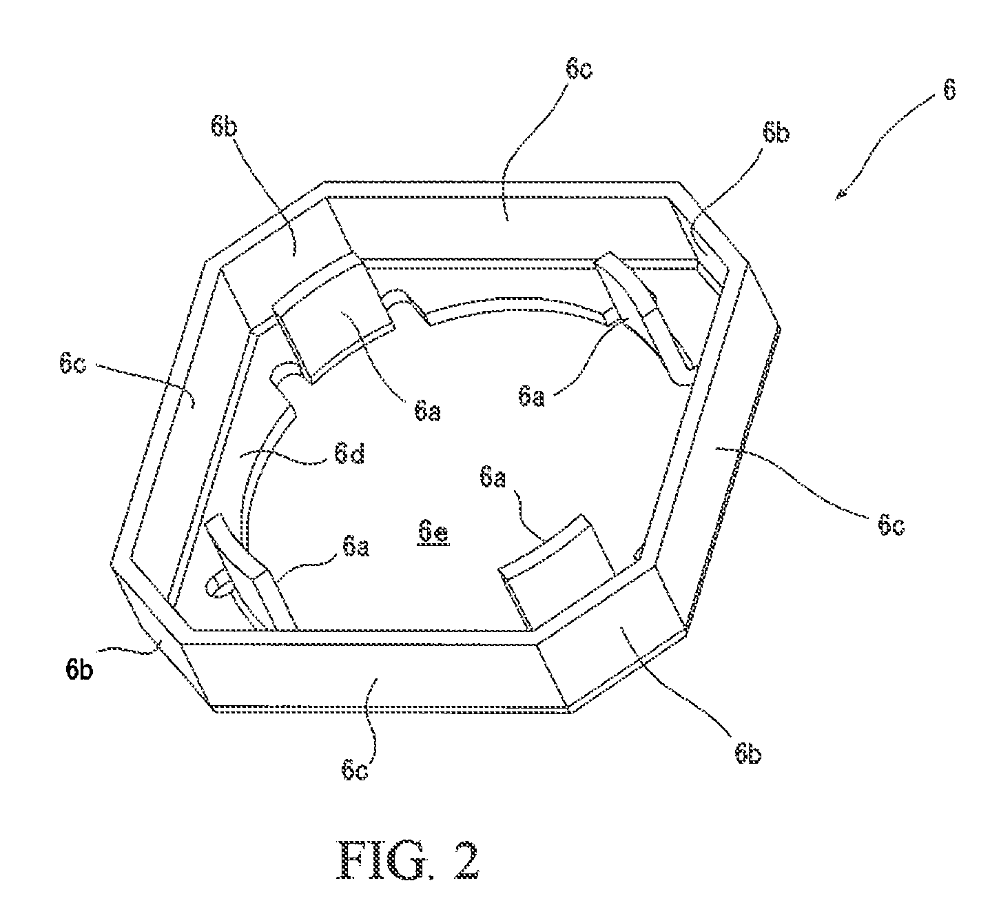
[0029]An actuator assembly 1 of a camera module according to the embodiment includes: a lens unit which constitutes an optical system of the camera module (not shown in the drawings); a holder 9 which houses the lens unit therein and is displaceable along the optical axis direction of the lens unit, the holder 9 having a roughly cylindrical shape having upper and lower cylindrical end portions; a coil 8 provided on the holder and formed to have an octagon shape in its horizontal cross section having eight outside surface portions; a yoke 6 having an outer wall portion formed to have an octagon shape in its horizontal cross section which is similar to and larger than the octagon shape of the coil 8 and having eight magnet mounting inner surfaces; eight flat plate-shaped magnets 7 (7a, 7b) respectively provided on the magnet mounting inner surfa...


PUM


Abstract

A camera module that can be used in small-sized electronic apparatuses such as digital cameras, camera-equipped cellular phones and the like is provided. The camera module includes a lens unit which constitutes an optical system of the camera module; a holder which houses the lens unit and is displaceable along an optical axis direction of the lens unit; a coil provided on the holder, the coil being formed to have an octagon shape in its horizontal cross section having eight outside surface portions; a yoke having an outer cylindrical wall portion formed to have an octagon shape in its horizontal cross section which is similar to and larger than the octagon shape of the coil and having eight magnet mounting inner surfaces; eight flat plate-shaped magnets respectively provided on the magnet mounting inner surfaces of the yoke for providing a magnetic field to the coil in cooperation with the yoke, each of the eight flat plate-shaped magnets being arranged so as to face each of the outside surface portions of the coil through a predetermined constant spacing; upper and lower leaf springs respectively attached to upper and lower cylindrical end portions of the holder for supporting the holder so as to be displaceable along the optical axis direction of the lens unit; and a base for supporting the yoke and the lower spring.

Description

BACKGROUND OF THE INVENTION[0001]1. Field of the Invention[0002]This invention relates to a camera module, and more specifically to a camera module that can be used in small-sized electronic apparatuses such as digital cameras, camera-equipped cellular phones and the like.[0003]2. Description of the Prior Art[0004]A camera module having a function of displacing a lens unit in a direction of an optical axis of the lens unit is used in relatively small-sized digital cameras, camera-equipped cellular phones and the like. This function is used for providing an autofocus function and / or zoom function, and is achieved by an interaction between a magnetic field generated by an electrical current flowing in a coil and a magnetic field generated by a yoke and magnets provided on the yoke. Recently, camera modules to be mounted in camera-equipped cellular phones are required to further reduce size and shape thereof.[0005]FIG. 4 shows an actuator assembly for providing an autofocus function us...

Claims


Application Information

Patent Timeline
Patent Type & Authority Applications(United States)
IPC IPC(8): G02B7/04
CPCG02B7/102H02K41/0356G02B13/009
Inventor HONMA, TOSHIHIKO
Owner MITSUMI ELECTRIC CO LTD
Why Eureka
Try Eureka