Light emitting diode modules for illuminated panels

a technology of light-emitting diodes and illuminated panels, which is applied in the field of illumination panels, can solve the problems of large packages, large size of the package, and large perceived light intensity near the center of the panel, and achieves the effects of low maintenance, low cost, and very efficient operation

Inactive Publication Date: 2008-08-07
ILLUMINER
View PDF34 Cites 20 Cited by
  • Summary
  • Abstract
  • Description
  • Claims
  • Application Information

AI Technical Summary

Benefits of technology

[0008]To achieve the foregoing and in accordance with the present invention, light emitting diode (LED) modules for illuminating panels such as advertising display panels are provided. Such LED modules can be operated very efficiently, cost-effectively and with minimal maintenance once installed in the field.
[0010]The interface between the inner and outer beam directors can be curved or substantially flat. For example, interface can be parabolic, elliptical or cone-shaped. The N value of the inner beam director is lower than the N value of the outer beam director thereby enabling the LED module to generate a substantially narrow beam of light.

Problems solved by technology

However, as the panel size increases, the edge lighting has to travel further into the panel and hence the perceived light intensity near the center of the panel tends to appear substantially dimmer then that near the edge of the panel.
Since, most casual observers are able to perceive differences in light intensity substantially greater than 20%, this unevenness in light intensity is particularly acute with large panels commonly used for advertising.
Unfortunately, the resulting package is now larger, and other problems may also result such as lens adhesion and Fresnel losses associated with the additional lens and adhesive.

Method used


Image

  • Light emitting diode modules for illuminated panels
  • Light emitting diode modules for illuminated panels
  • Light emitting diode modules for illuminated panels

Examples


Embodiment Construction

[0030]The present invention will now be described in detail with reference to several embodiments thereof as illustrated in the accompanying drawings. In the following description, numerous specific details are set forth in order to provide a thorough understanding of the present invention. It will be apparent, however, to one skilled in the art, that the present invention may be practiced without some or all of these specific details. In other instances, well known process steps and / or structures have not been described in detail in order to not unnecessarily obscure the present invention. The features and advantages of the present invention may be better understood with reference to the drawings and discussions that follow.

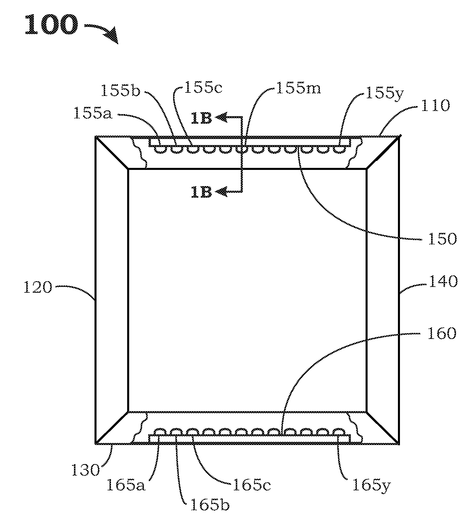
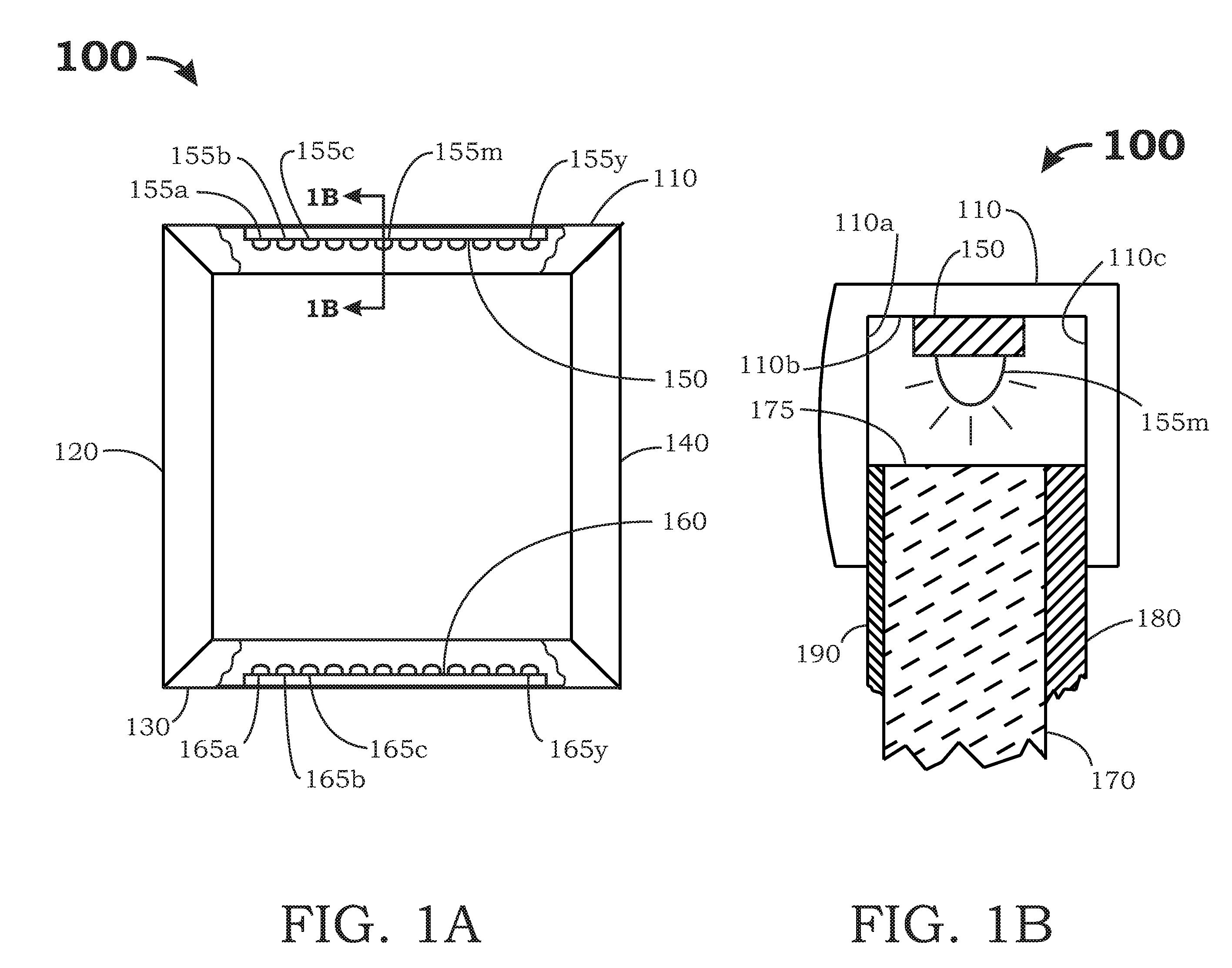
[0031]FIG. 1A is a front view showing one embodiment of an illuminated panel 100 in accordance with the present invention. Panel 100 includes frame members 110, 120, 130, 140. To facilitate discussion, the front portion of top frame member 110 and the front port...


PUM


Abstract

LED modules are provided for efficiently illuminating edge illuminated panels. Each LED module includes a base, an LED located substantially within the base, an inner beam director, and an outer beam director. An interface between the inner beam director and the outer beam director is shaped to refract and / or reflect the light beam along the interface, thereby narrowing a substantial portion of the light beam generated by the LED. For light output efficiency, each LED can have a geometrically coated phosphor layer which produces a whiter light beam. The interface between the inner and outer beam directors can be curved and / or substantially flat. The N value of the inner beam director is generally lower than the N value of the outer beam director thereby enabling the LED module to generate a substantially narrow beam of light. In some embodiments, the interface between the inner beam director and the outer beam director includes an intermediate beam director configured to further refract and / or reflect the light beam generated by the LED.

Description

CROSS REFERENCE TO RELATED APPLICATIONS[0001]This application is related to co-pending and concurrently filed application Ser. No. ______, (Attorney Docket Number IM 0603) filed Feb. 3, 2007, entitled “Edge-Illuminated Panels With Shaped-Edge Diffuser”, by George K. Awai, Michael D. Ernst and Alain S. Corcos, which is incorporated by reference herein for all purposes.BACKGROUND OF THE INVENTION[0002]This invention relates generally to illuminating panels. More particularly, this invention relates to light emitting diode (LED) modules for edge illuminated panels.[0003]Illuminated panels have many uses where evenly lit panels with neutral color temperature are used including advertising display panels, shopping mall directories, restaurant menus, event schedules, and navigational signboards. Other uses for illuminated panels include light-boxes for artists, photographers, architects, design engineers, general contractors and draftsmen.[0004]These illuminated panels can be as small as ...

Claims


Application Information

Patent Timeline
Patent Type & Authority Applications(United States)
IPC IPC(8): F21V7/04
CPCG02B6/002G02B6/0031G02B6/0055G02B6/0068H01L33/60G02B6/0085H01L33/54H01L33/56G02B6/0073
Inventor AWAI, GEORGE K.ERNST, MICHAEL D.CORCOS, ALAIN S.
Owner ILLUMINER
Why Eureka
Try Eureka