Communications apparatus and frame control method

a communication apparatus and frame control technology, applied in electrical apparatus, digital transmission, data switching networks, etc., can solve the problems of inability to increase the communication bandwidth, use of nics, and inability to ensure the order in which the frame arrives at the receiving apparatus, so as to improve the efficiency of data transfer

Inactive Publication Date: 2008-08-07
FUJITSU LTD
View PDF5 Cites 32 Cited by
  • Summary
  • Abstract
  • Description
  • Claims
  • Application Information

AI Technical Summary

Benefits of technology

[0015]The method may also be configured in such a way that, when the receiving apparatus detects, by analyzing the order information in each received frame, that a frame which should have been received immediately before a newly received frame has not received, a timer is activated; the newly received frame is forwarded to the processing unit in the upper layer when the frame which should have been received immediately before the newly received frame is received within a predetermined time after the activation of the timer; and the newly received frame is discarded when the frame which should have been received immediately before the newly received frame is not received within the predetermined time after the activation of the timer. Even when the frames are not received in the order in which the frames have been transmitted, when the frames are received within a predetermined time, the frames are forwarded to the processing unit in the upper layer in the appropriate order. The configuration prevents the upper layer from issuing a re-transmitting request due to the inversion of the frame order.
[0016]According to the present invention, the prevention of the occurrence of an unnecessary data re-transmission process makes it possible to improve the data transfer efficiency.

Problems solved by technology

Therefore, focusing a given piece of data, its transmission between the communications apparatuses is performed through a single path, making it impossible to increase the communication bandwidth.
However, since the data frame is transmitted through a plurality of transmission paths, the order in which the frame arrived at the receiving apparatus cannot be assured.
Moreover, all of the four methods have the problem that the more NICs are used, the higher the CPU utilization.

Method used


Image

  • Communications apparatus and frame control method
  • Communications apparatus and frame control method
  • Communications apparatus and frame control method

Examples


Embodiment Construction

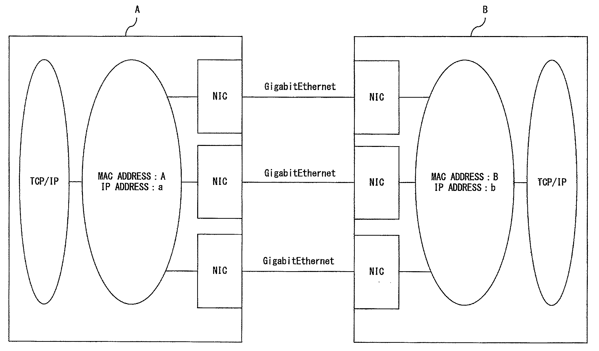
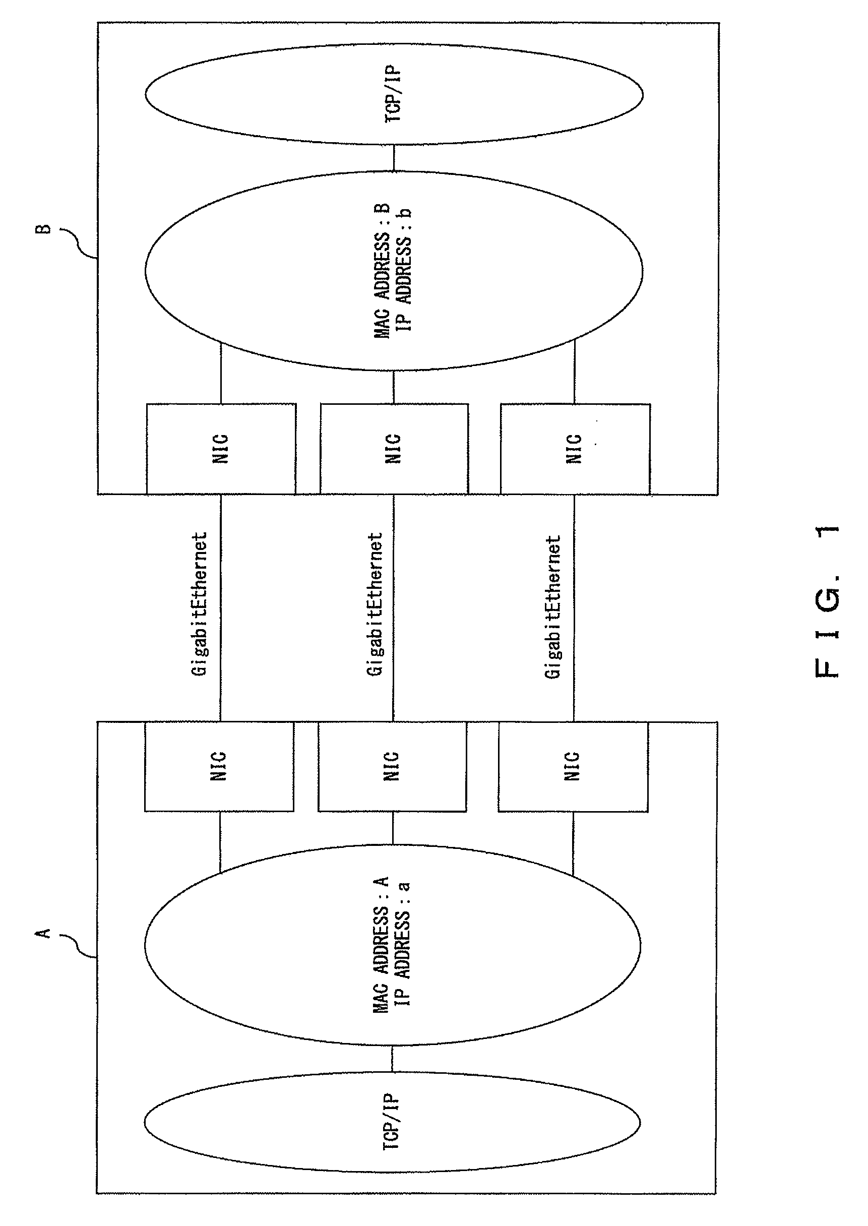
[0030]FIG. 1 is a configuration diagram of a communications system equipped with a general multipath function. For illustrative purpose, a communications system A is assumed as the data transmission side, and a communications system B is assumed as the data reception side. The communications systems at both transmission side and reception side are equipped with the multipath function. The multipath function herein refers to the function to transmit / receive data by setting a plurality of paths between communications apparatuses. The multipath function may also include a function to switch the communication paths and continue the communication, when a failure and the like is detected in a transmission path or an NIC in a system where the transmission paths between the NICs and a switching hub are made redundant with a plurality of NICs.

[0031]For example, when both of the communications systems A and B use the multilink Ethernet method, a plurality of (three, in FIG. 1) NICs are simult...


PUM


Abstract

In a frame control method in a communications system providing a multipath function for controlling a frame having a header area and a data area, attaching, in a transmission apparatus, order information indicating a transmission order to the data area of the frame; outputting, from the transmission apparatus to a network, the frame with the attached order information, through a path selected from a plurality of paths; reading out, in a receiving apparatus, the order information from the data area of the frame received through the network; and determining, in the receiving apparatus, whether or not to transfer the received frame to a processing unit in an upper layer to process control information stored in the header area of the frame, in accordance with the read-out order information.

Description

CROSS REFERENCE TO RELATED APPLICATION[0001]This application is a continuation of international PCT application No. PCT / JP2005 / 021995 filed on Nov. 30, 2005.BACKGROUND OF THE INVENTION[0002]1. Field of the Invention[0003]The present invention relates to a technology for transmitting and receiving data in a communications system equipped with a multipath function.[0004]2. Description of the Related Art[0005]A communications system equipped with a multipath function in which a plurality of paths for data transmission / reception are provided between communication apparatuses has come into practical use. For example, the multipath method and the multilink Ethernet method are known for realizing the multipath function.[0006]The multipath method realizes the multilink by using a plurality of Network Interface Cards (hereinafter referred to as NICs), making the transmission paths between NICs and a switching hub redundant and using a NIC exclusively, thereby realizing the multilink.[0007]Th...

Claims


Application Information

Patent Timeline
Patent Type & Authority Applications(United States)
IPC IPC(8): H04L12/56H04L45/243H04L47/43
CPCH04L12/4625H04L45/00H04L69/14H04L47/10H04L47/34H04L45/24
Inventor SHIHARA, SHINJITAKEDA, KENICHIRO
Owner FUJITSU LTD
Why Eureka
Try Eureka